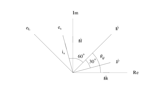
GLE Example: flux_linkage_space_vector_diagram.gle

[PDF file]
! Space phasor diagram for flux linkage estimator
size 12 7


! Arc with arrows on both ends
sub arcarrow radius ang1 ang2 fntheight
	arc radius ang1 ang2 arrow end
end sub

begin scale 0.1 0.1

	amove 60 10
	begin origin ! 0,0 now at 50,10 (common point)
		! Lines with arrows
		! may need set hei for arrow sizes
		arrow_size = 7
		set hei arrow_size

		! Real axis
		set lstyle 1
		rline 45 0
		amove 0 0

		! Imag Axis
		set lstyle 1
		rline 0 45
		amove 0 0

		! \psi_s
		set lstyle 1
		rline 32*cos(torad(15)) 32*sin(torad(15)) arrow end
		amove 0 0

		! \psi_L
		set lstyle 1
		rline 45*cos(torad(45)) 45*sin(torad(45)) arrow end
		amove 0 0

		! e_s
		set lstyle 1
		rline -32*cos(torad(75)) 32*sin(torad(75)) arrow end
		amove 0 0

		! e_L
		set lstyle 1
		rline -45*cos(torad(45)) 45*sin(torad(45)) arrow end
		amove 0 0

		! Angle measurements
		@arcarrow 23 0 45 arrow_size
		@arcarrow 15 15 45 arrow_size
		@arcarrow 12 45 105 arrow_size

		! Arrows on axes
		set lstyle 1
		amove 25 0
		rline 5 0 arrow end
		amove 0 25
		rline 0 5 arrow end
		amove -20*cos(torad(75)) 20*sin(torad(75))
		rline -5*cos(torad(75)) 5*sin(torad(75)) arrow end
		set lstyle 1

		! Text
		set just CL
		set hei 4
		amove 50 0
		text Re
		amove 0 50
		text Im

		amove 37*cos(torad(15)) 37*sin(torad(15))
		text \psi_s

		amove 26*cos(torad(30)) 26*sin(torad(30))
		text \theta_{\psi_L}

		amove 50*cos(torad(45)) 50*sin(torad(45))
		set just BL
		text \psi_L

		amove 27.5*cos(torad(-5)) 27.5*sin(torad(-5))
		set just TC
		text \psi_{LR}

		amove 27.5*cos(torad(80)) 27.5*sin(torad(80))
		set just CL
		text \psi_{LI}

		amove  -20*cos(torad(70)) 20*sin(torad(70))
		set just TR
		text i_s

		amove -37*cos(torad(75)) 37*sin(torad(75))
		set just BR
		text e_s

		amove -50*cos(torad(45)) 50*sin(torad(45))
		set just BR
		text e_L

		amove 16*cos(torad(30)) 16*sin(torad(30))
		set just BL
		text 30^{\circ}

		amove 14*cos(torad(60)) 14*sin(torad(60))
		set just BC
		text 60^{\circ}

	end origin
end scale
[Return to examples page]
