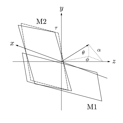
GLE Example: mirrors.gle

[PDF file]
size 10 10
set font texcmmi

!  There are two problems here. First, given the appropriate dimensions
!  and angle, we need to determine the actual positions of the
!  important points. It might also be handy to calculate the other
!  angles, although I doubt I'd use them since I'm principally
!  concerned with obtaining a general diagram. I then need to determine
!  the projected values of these points for a 2d representation.

!   Firstly, then, I need to work out the actual points. I'll use two
!   mirrors of dimensions Lx2L. One has a horizontal edge, the other a
!   vertical one. Inclinations are given by theta and phi, and at some
!   point later I then need to work out tau, I think.

! Angle of orthonormal projection of axis out of screen
proj_angle=-70

! Inclination to horizontal plane
theta_deg=15
theta=torad(theta_deg)

! Rotation about vertical (y) axis
phi_deg=-20
phi=torad(phi_deg)

! "Yaw"
! This rotation about the mirror normal (initially the z-axis) ensures
! that the long edge of M2 runs in a plane parallel to the y-z
! plane. This means that a beam along the z-axis will always percieve
! this edge as vertical.
tau=atan(sin(theta)*tan(phi))

! Mirror dimension (Lx2L)
L=2.5
! Axis length
axis_l=4
! Mirror separation
d=0.5

!-------------------------------------------
! Horizontal and vertical vector for mirror M1
h1_x=1
h1_y=0
h1_z=0
v1_x=0
v1_y=1
v1_z=0

! Horizontal and vertical vector for mirror M2
h2_x=1
h2_y=0
h2_z=0
v2_x=0
v2_y=1
v2_z=0

! Mirror normal unit vector
n_x=0
n_y=0
n_z=-1

!   Rotations should be applied in the order theta (about x), phi
!   (about y), and tau is either first or last, depending on how it is
!   worked out. (Actually, do tau first)

sin_phi = sin(phi)
cos_phi = cos(phi)
sin_theta = sin(theta)
cos_theta = cos(theta)

! Rotate about z-axis
sub rotate_tau x y z
x_new=x*cos(tau)-y*sin(tau)
y_new=x*sin(tau)+y*cos(tau)
z_new=z
end sub

! Rotate about x-axis
sub rotate_theta x y z
x_new=x
y_new=z*sin_theta+y*cos_theta
z_new=z*cos_theta-y*sin_theta
end sub

! Rotate about y-axis
sub rotate_phi x y z
x_new=x*cos_phi-z*sin_phi
y_new=y
z_new=x*sin_phi+z*cos_phi
end sub

! 1) Rotate M2 vectors about z

@rotate_tau h2_x h2_y h2_z
h2_x=x_new
h2_y=y_new
h2_z=z_new

@rotate_tau v2_x v2_y v2_z
v2_x=x_new
v2_y=y_new
v2_z=z_new

! 2) Rotate both mirrors and normal about x

@rotate_theta h1_x h1_y h1_z
h1_x=x_new
h1_y=y_new
h1_z=z_new
@rotate_theta v1_x v1_y v1_z
v1_x=x_new
v1_y=y_new
v1_z=z_new

@rotate_theta h2_x h2_y h2_z
h2_x=x_new
h2_y=y_new
h2_z=z_new
@rotate_theta v2_x v2_y v2_z
v2_x=x_new
v2_y=y_new
v2_z=z_new

@rotate_theta n_x n_y n_z
n_x=x_new
n_y=y_new
n_z=z_new

! 3) Rotate both mirrors and normal about y

@rotate_phi h1_x h1_y h1_z
h1_x=x_new
h1_y=y_new
h1_z=z_new
@rotate_phi v1_x v1_y v1_z
v1_x=x_new
v1_y=y_new
v1_z=z_new

@rotate_phi h2_x h2_y h2_z
h2_x=x_new
h2_y=y_new
h2_z=z_new
@rotate_phi v2_x v2_y v2_z
v2_x=x_new
v2_y=y_new
v2_z=z_new

@rotate_phi n_x n_y n_z
n_x=x_new
n_y=y_new
n_z=z_new

!    Need to produce an othographic projection of my diagram.
!    To achieve this map:
!    z -> 0
!    y -> y + Bx
!    x -> z + Ax
!    Where A and B could be defined by some angle and scaling factor.

A=1*sin(torad(proj_angle))
B=1*cos(torad(proj_angle))

! This subroutine takes in the 3d co-ordinates and gives the projected
! 2d co-ords as x_render and y_render - use these immediately as they
! are liable to change.
x_render=0
y_render=0
sub render x y z
x_render=z+A*x
y_render=y+B*x
end sub

! amove, aline, rmore, rline in projected space:
sub pamove x y z
amove z+A*x y+B*x
end sub

sub prmove x y z
rmove z+A*x y+B*x
end sub

sub paline x y z
aline z+A*x y+B*x
end sub

sub prline x y z
rline z+A*x y+B*x
end sub

sub paline_arrow x y z
aline z+A*x y+B*x arrow end
end sub

sub prline_arrow x y z
rline z+A*x y+B*x arrow end
end sub

! Now let's start drawing!

! Work out unit normal vectors for later
@render n_x n_y n_z
n_rx=x_render
n_ry=y_render

amove 5 5
begin origin

!------------------------------------
! First of all, let's do the axes

set hei 0.6

! x-axis
@pamove -axis_l 0 0
@paline_arrow axis_l 0 0
@prmove 0.3 0 0
set just cc
text x

! y-axis
@pamove 0 -axis_l 0
@paline_arrow 0 axis_l 0
@prmove 0 0.3 0
set just cc
text y

! z-axis
@pamove 0 0 -axis_l
@paline_arrow 0 0 axis_l
@prmove 0 0 0.3
set just cc
text z

!-----------------------------------

!Mirror M1

amove 0 0
! Given that I've got the unit vector I could even separate the two
! mirrors by a multiple of this distance.
rmove 0.5*d*n_rx 0.5*d*n_ry
@prline L*h1_x L*h1_y L*h1_z
@prline -L*v1_x -L*v1_y -L*v1_z
@prline -2*L*h1_x -2*L*h1_y -2*L*h1_z
@prline L*v1_x L*v1_y L*v1_z
@prline L*h1_x L*h1_y L*h1_z
! Label
@prmove -0.7*L*h1_x -0.7*L*h1_y -0.7*L*h1_z
@prmove -1.3*L*v1_x -1.3*L*v1_y -1.3*L*v1_z
gsave
set font texcmr
text M1
grestore

!Mirror M2 - without yaw
set lstyle 3
amove 0 0
rmove -0.5*d*n_rx -0.5*dL*n_ry
@prline L*v1_x L*v1_y L*v1_z
gsave
@prmove 0.05*L*h1_x 0.15*L*v1_y 0.15*L*v1_z
set hei 0.45
text \tau
grestore
@prline L*h1_x L*h1_y L*h1_z
@prline -2*L*v1_x -2*L*v1_y -2*L*v1_z
@prline -L*h1_x -L*h1_y -L*h1_z
@prline L*v1_x L*v1_y L*v1_z

! With yaw
set lstyle 0
amove 0 0
rmove -0.5*d*n_rx -0.5*dL*n_ry
@prline L*v2_x L*v2_y L*v2_z
@prline L*h2_x L*h2_y L*h2_z
@prline -2*L*v2_x -2*L*v2_y -2*L*v2_z
@prline -L*h2_x -L*h2_y -L*h2_z
@prline L*v2_x L*v2_y L*v2_z
! Label
@prmove 0.3*L*h2_x 0.3*L*h2_y 0.3*L*h2_z
@prmove 1.3*L*v2_x 1.3*L*v2_y 1.3*L*v2_z
gsave
set font texcmr
text M2
grestore

! Normal vector
set lstyle 0
amove 0 0
@paline_arrow -1.5*L*n_x -1.5*L*n_y -1.5*L*n_z
! Show projections onto horizontal plane, and x, y and z axes
set lstyle 2
!gsave
!@paline 0 -1.5*L*n_y 0
!grestore
gsave
@paline 0 0 -1.5*L*n_z
@prmove -L*n_x -L*n_y -0.2*L*n_z
set hei 0.45
text \alpha
grestore
gsave
@prmove 0 1*L*n_y 0.2*L*n_z
set hei 0.45
text \theta
@prmove 0 0.9*L*n_y -0.15*L*n_z
text \phi
grestore
@paline -1.5*L*n_x 0 -1.5*L*n_z
gsave
aline 0 0
grestore
!gsave
!@paline -1.5*L*n_x 0 0
!grestore
gsave
@paline 0 0 -1.5*L*n_z
grestore
end origin

! Possible improvements
! 1) Need to clean-up axis label positions (only normal)
! 2) Shade in mirrors? Might need extra heuristics for overlapping
!    regions
! 3) Label angles phi, theta, tau, alpha and distance d
[Return to examples page]
