Diagrams
Diagrams, drawings, or other artwork
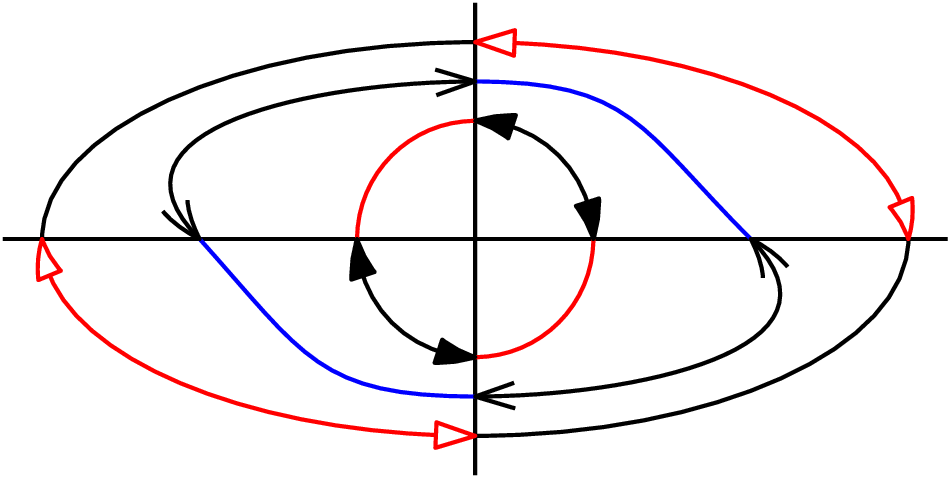
arrowdesign.gle
arrowdesign.gle
size 12.5 5

include "shape.gle"

set arrowangle 15 arrowsize 0.25 lwidth 0.02

sub boxline x1 y1 x2 y2 d
   amove x1 y1
   circle 0.05 fill black
   local l = sqrt((x2-x1)^2+(y2-y1)^2)
   begin rotate xy2angle(x2-x1,y2-y1)
      rmove 0 -d/2
      box l d
   end rotate
   amove x2 y2
   circle 0.05 fill black
end sub

sub lrarrow x1 y1 x2 y2 d str$
   set color red
   amove x1 y1
   aline x2 y2 arrow both
   set color black
   line_label x1 y1 x2 y2 str$ d
end sub

l = 6; t = 15
amove 10 2.5
begin origin
   boxline -l*cos(torad(t))  l*sin(torad(t)) 0 0 1
   boxline -l*cos(torad(t)) -l*sin(torad(t)) 0 0 1
   boxline -9.5 0 -0.5/sin(torad(t)) 0 1
   amove 0.5*cos(torad(90-t))  0.5*sin(torad(90-t))
   aline 0.5/sin(torad(t)) 0
   amove 0.5*cos(torad(90-t)) -0.5*sin(torad(90-t))
   aline 0.5/sin(torad(t)) 0
   set color red lstyle 2
   amove -0.5/sin(torad(t)) 0
   rline 0 -2
   amove 0  0
   rline 0 -2
   amove +0.5/sin(torad(t)) 0
   rline 0 -2
   amove 0  0
   aline -l 0
   amove 0  0
   aline -l*cos(torad(t)) l*sin(torad(t))
   set lstyle 1
   amove 0 0
   arc   5.5 180-t 180 arrow both
   amove 5.6*cos(torad(180-t/2)) 5.6*sin(torad(180-t/2))
   set just rc color black
   tex "$\alpha$"
   amove -l 0
   circle 0.05 fill black
   lrarrow -7 -0.5 -7 0.5 -0.1 "\tex{$d$}"
   lrarrow -0.5/sin(torad(t)) -1.75 0 -1.75 -0.1 "\tex{$\frac{d/2}{\mathrm{sin} \alpha}$}"
   lrarrow 0 -1.75 0.5/sin(torad(t)) -1.75 -0.1 "\tex{$\frac{d/2}{\mathrm{sin} \alpha}$}"
end origin

amove 0.1 0.1
set just bl
tex "GLE arrow design"
arrowstyle.gle
arrowstyle.gle
size 12 6

set arrowsize 1 arrowangle 15

set color red lstyle 2
amove 4.5 0.5
aline 4.5 pageheight()-0.5
set color green lstyle 2
amove 3.5 0.5
aline 3.5 pageheight()-0.5
amove 6 0.5
aline 6 pageheight()-0.5
set color red lwidth 0.1 lstyle 1
amove 5 0.5
aline 5 pageheight()-0.5
set color black lstyle 1

set arrowstyle filled
amove 0.5 3
aline 4.5 3 arrow end

set arrowstyle empty
amove 0.5 4
aline 4.5 4 arrow end

set arrowstyle simple
amove 0.5 5
aline 4.5 5 arrow end

set font texcmr hei 0.4 just bc
amove 2 3.2
write "filled"

amove 2 4.2
write "empty"

amove 2 5.2
write "simple"

set join round

set arrowstyle filled
amove 4.5 0.5
arc 1.5 90 180 arrow start

set arrowstyle filled arrowtip round
amove 8 3
aline 5 3 arrow end

set arrowstyle empty
amove 8 4
aline 5 4 arrow end

set arrowstyle simple
amove 8 5
aline 5 5 arrow end

set arrowstyle filled
amove 5 0.5
arc 1.5 0 90 arrow end

sub arrow_curved angle open size
   local xp = xpos()
   local yp = ypos()
   local dy = size*sin(torad(open))
   begin rotate angle
      begin path stroke fill black
         rmove size-size/4 0
         rline size/4 dy
         aline xp    yp curve 180     open/2 0.5*size 0.5*size
         rline size -dy curve -open/2 180    0.5*size 0.5*size
         closepath
      end path
   end rotate
   amove xp yp
end sub

set arrowstyle curved lwidth 0.05 arrowsize 0.5

for angle = 0 to 360 step 45
   amove 10 2
   aline 10+1.5*cos(torad(angle)) 2+1.5*sin(torad(angle)) arrow end
next angle
bayesiannet.gle
bayesiannet.gle
size 14.5 5.75

set texlabels 1
x0 = 4.75;  y0 = 5
xdel = 3.5; ydel = 2

include "ellipse.gle"

set_ellipse_c 0.35
set_shape_dxdy 0.15 0.15
set fill wheat

ellipse_text x0      y0        "Burglary"   burglary
ellipse_text x0+xdel y0        "Earthquake" earthquake
ellipse_text x0      y0-2*ydel "John calls" john
ellipse_text x0+xdel y0-2*ydel "Mary calls" mary

set fill darksalmon
ellipse_text x0+xdel*0.5 y0-ydel "Alarm" alarm

set hei 0.35 arrowsize 0.27
join burglary.ci   -> alarm.ci
join earthquake.ci -> alarm.ci
join alarm.ci      -> john.ci
join alarm.ci      -> mary.ci

set just rc
amove pointx(burglary.lc)-0.5 pointy(burglary.lc)
begin tex
    \begin{tabular}{|l|l|}   \hline
    B          & 0.05     \\ \hline
    $\lnot\:$B & 0.95     \\ \hline
    \end{tabular}
end tex

amove pointx(john.lc)-0.5 pointy(john.lc)
begin tex
    \begin{tabular}{|l|l|l|}       \hline
               & A & $\lnot\:$A \\ \hline
    J          & 0.8 & 0.1      \\ \hline
    $\lnot\:$J & 0.2 & 0.9      \\ \hline
    \end{tabular}
end tex

set just lc
amove pointx(mary.rc)+0.5 pointy(mary.rc)
begin tex
    \begin{tabular}{|l|l|l|}         \hline
               & A   & $\lnot\:$A \\ \hline
    M          & 0.9 & 0.2        \\ \hline
    $\lnot\:$M & 0.1 & 0.8        \\ \hline
    \end{tabular}
end tex

amove pointx(earthquake.rc)+0.5 pointy(earthquake.rc)
begin tex
    \begin{tabular}{|l|l|}   \hline
    E          & 0.01     \\ \hline
    $\lnot\:$E & 0.99     \\ \hline
    \end{tabular}
end tex

amove pointx(alarm.rc)+0.5 pointy(alarm.rc)
begin tex
    \begin{tabular}{|l|l|l|l|l|}                                              \hline
               & B,E & B,$\lnot\:$E & $\lnot\:$B,E & $\lnot\:$B,$\lnot\:$E \\ \hline
    A          & 0.9 & 0.8          & 0.4          & 0.01                  \\ \hline
    $\lnot\:$A & 0.1 & 0.2          & 0.6          & 0.99                  \\ \hline
    \end{tabular}
end tex
brilzone.gle
brilzone.gle
!
! Brillouin zone of the face-centered cubic lattice
! by P. Straube, Experimentalphysik 2, Univ. Kassel, Germany
!

size 12 9
amove 6 1
set font texcmr hei 0.3

begin origin
   begin scale 1.1 1.1
      xten=.5
      amove 0.000 2.788
      xa=xpos()
      ya=ypos()
      xe=0.00
      ye=5.575
      set lstyle 2
      aline xe ye
      set lstyle 1
      rline xten*(xe-xa) xten*(ye-ya) arrow end
      rmove .2 -.2
      text [001]
      set lstyle 2
      amove 0.000 2.788
      xe=-0.686
      ye=2.324
      xa=xpos()
      ya=ypos()
      aline xe ye
      set lstyle 1
      rline xten*(xe-xa) xten*(ye-ya) arrow end
      rmove .2 -.2
      text [100]
      set lstyle 2
      amove 0.000 2.788
      xa=xpos()
      ya=ypos()
      xe=2.744
      ye=2.672
      aline xe ye
      set lstyle 1
      rline xten*(xe-xa) xten*(ye-ya) arrow end
      rmove .2 -.2
      text [010]
      set lstyle 2
      begin path stroke fill shade1
         amove 0.000 2.788
         aline 1.543 2.353
         aline 0.514 5.431
         aline 0.000 5.575
         aline 0.000 2.788
      end path
      begin path stroke fill shade2
         amove 0.000 2.788
         aline 1.543 2.353
         set lstyle 1
         aline 0.686 2.266
         set lstyle 2
         aline -0.686 2.324
         aline 0.000 2.788
      end path
      set lstyle 1
      amove -.3 2.788
      text \Gamma
      amove 1.55 2.2
      text K
      amove 0.68 2
      text W
      amove -.986 2.32
      text X
      amove 1.0285 3.892
      text L
      amove .6 5.2
      text U
      amove -.3 5.5
      text X
      set lstyle 2
      set lstyle 1
      amove -0.343 5.344
      aline -1.372 5.633
      aline 0.343 5.807
      aline 1.372 5.517
      aline -0.343 5.344
      amove -0.343 -0.232
      aline -0.686 0.930
      aline -2.058 2.382
      aline -3.087 2.672
      aline -2.744 1.510
      aline -1.372 0.058
      aline -0.343 -0.232
      amove -2.058 2.382
      aline -0.686 3.718
      aline -0.343 5.344
      aline -1.372 5.633
      aline -2.744 4.298
      aline -3.087 2.672
      aline -2.058 2.382
      amove -0.343 -0.232
      aline -0.686 0.930
      aline 0.686 2.266
      aline 2.401 2.440
      aline 2.744 1.278
      aline 1.372 -0.058
      aline -0.343 -0.232
      amove 0.686 2.266
      aline -0.686 3.718
      aline -0.343 5.344
      aline 1.372 5.517
      aline 2.744 4.066
      aline 2.401 2.440
      aline 0.686 2.266
      amove 2.744 1.278
      aline 3.087 2.904
      aline 2.744 4.066
   end scale
end origin
cavity.gle
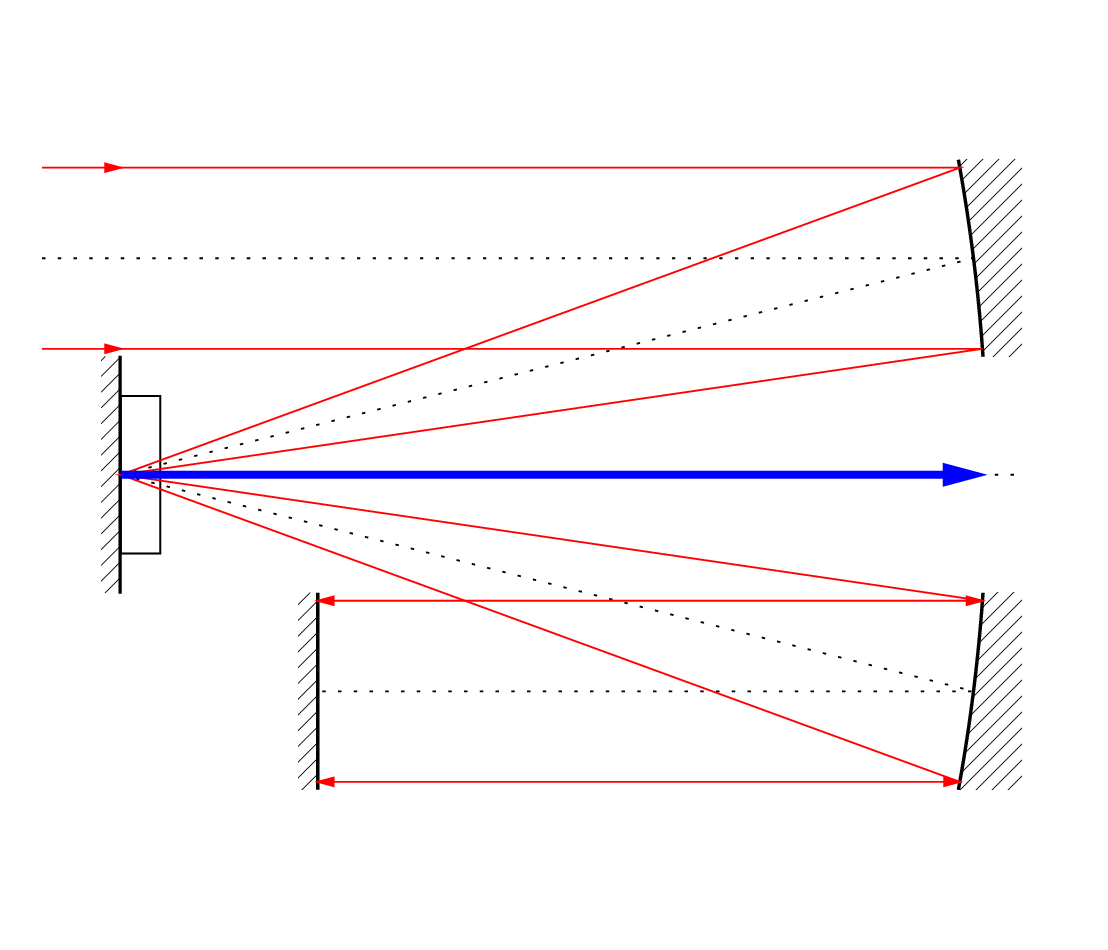
cavity.gle
size 14 12

set hei 0.6 ! Make arrows smaller

sub parmove focus_x focus_y length new_y
! length is distance to right of focus
    new_x=length-sqr(new_y-focus_y)/(4*length)+focus_x
    amove new_x new_y
end sub

sub parline focus_x focus_y length new_y
! length is distance to right of focus
    new_x=length-sqr(new_y-focus_y)/(4*length)+focus_x
    aline new_x new_y
end sub

sub parabola length start_y end_y
    parsteps = 20
    focus_x = xpos()
    focus_y = ypos()
    @parmove focus_x focus_y length start_y
    for i = 1 to parsteps step 1
        new_y=start_y+(end_y-start_y)*i/parsteps
        @parline focus_x focus_y length new_y
    next i
end sub

! Optical axes
amove 1.6 6
set lstyle 4
aline 13 6
amove 0.5 8.75
@parline 1.5 6 11 8.75
aline 1.5 6
@parline 1.5 6 11 3.25
aline 4 3.25
set lstyle 0

! mirror
amove 1 6
rmove 0.5 0
box 0.25 3 justify cr fill shade nobox name backmirror
box 0.02 3 justify cr fill black

! crystal
amove 1 6
rmove 0.5 0
box 0.5 2 justify cl name crystal

! top parabolic mirror
amove 1.5 6
begin path fill shade
    @parabola 11 7.5 10
    rline 0.8 0
    rline 0 -2.5
    closepath
end path
amove 1.5 6
set lwidth 0.04
@parabola 11 7.5 10

! bottom parabolic mirror
amove 1.5 6
begin path fill shade
    @parabola 11 4.5 2
    rline 0.8 0
    rline 0 2.5
    closepath
end path
amove 1.5 6
set lwidth 0.04
@parabola 11 4.5 2
set lwidth 0

! pump return mirror
amove 4 2
box 0.25 2.5 just br fill shade nobox
set lwidth 0.04
rline 0 2.5
set lwidth 0

!
! these beams may be best done first in order not cover optics.
!
! pump beam
set color red
!inside ray
amove 0.5 9.9
rline 1 0 arrow end
@parline 1.5 6 11 9.9
aline 1.5 6
@parline 1.5 6 11 2.1
aline 4 2.1 arrow both
! outside ray
amove 0.5 7.6
rline 1 0 arrow end
@parline 1.5 6 11 7.6
aline 1.5 6
@parline 1.5 6 11 4.4
aline 4 4.4 arrow both

! laser beam
set color blue
amove 1.5 6
set lwidth 0.1
rline 11 0 arrow end
set lwidth 0
colorspaces.gle
colorspaces.gle
!
! colorspaces.gle -demo of defining colors in alternate spaces RGB,HSV,CMYK etc.
!
size 7 7

dx=7
dy=7

!
! to define it in RGB space use CVTRGB function
! this function is not well documented
! basically it takes three numbers ranging from 0 to 1
! which define the RGB triplet
!
amove 1 1
set lwidth 0.1
for i=0 to 1 step 0.1
rmove 0.0 0.1
set color CVTRGB(0.5,0.9,i)
rline 5.0 0.0
rmove -5.0 0.0
next i

amove 1 3
set lwidth 0.1
for i=0 to 1 step 0.1
rmove 0.0 0.1
set color CVTRGB(i,0.9,0.2)
rline 5.0 0.0
rmove -5.0 0.0
next i


amove 1 5
set lwidth 0.1
for i=0 to 1 step 0.1
rmove 0.0 0.1
set color CVTRGB(0.5,i,0.2)
rline 5.0 0.0
rmove -5.0 0.0
next i
crispdm.gle
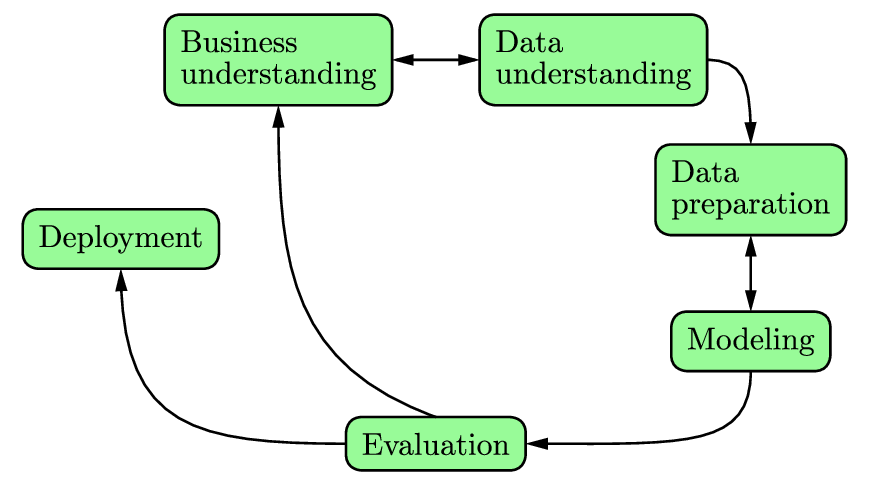
crispdm.gle
size 11 6

set lwidth 0.03 hei 0.4 just tc font texcmr arrowsize 0.27

amove 3.5 5.65
begin box add 0.2 round 0.2 name bi fill palegreen
   begin text
      Business
      understanding
   end text
end box

amove 7.5 5.65
begin box add 0.2 round 0.2 name du fill palegreen
   begin text
      Data
      understanding
   end text
end box

amove 9.5 4
begin box add 0.2 round 0.2 name dp fill palegreen
   begin text
      Data
      preparation
   end text
end box

set just cc

amove 9.5 1.7
begin box add 0.2 round 0.2 name mo fill palegreen
   text Modeling
end box

amove 5.5 0.4
begin box add 0.2 round 0.2 name ev fill palegreen
   text Evaluation
end box

amove 1.5 3
begin box add 0.2 round 0.2 name dep fill palegreen
   text Deployment
end box

join bi.rc <-> du.lc
join dp.bc <-> mo.tc
join du.rc  -> dp.tc  curve 0   90  0.5 0.75 ! angle & dist of Bezier control points
join mo.bc  -> ev.rc  curve 270 0   1   2
join ev.tc  -> bi.bc  curve 160 270 2   2
join ev.lc  -> dep.bc curve 180 270 2   2
curvedarrow.gle
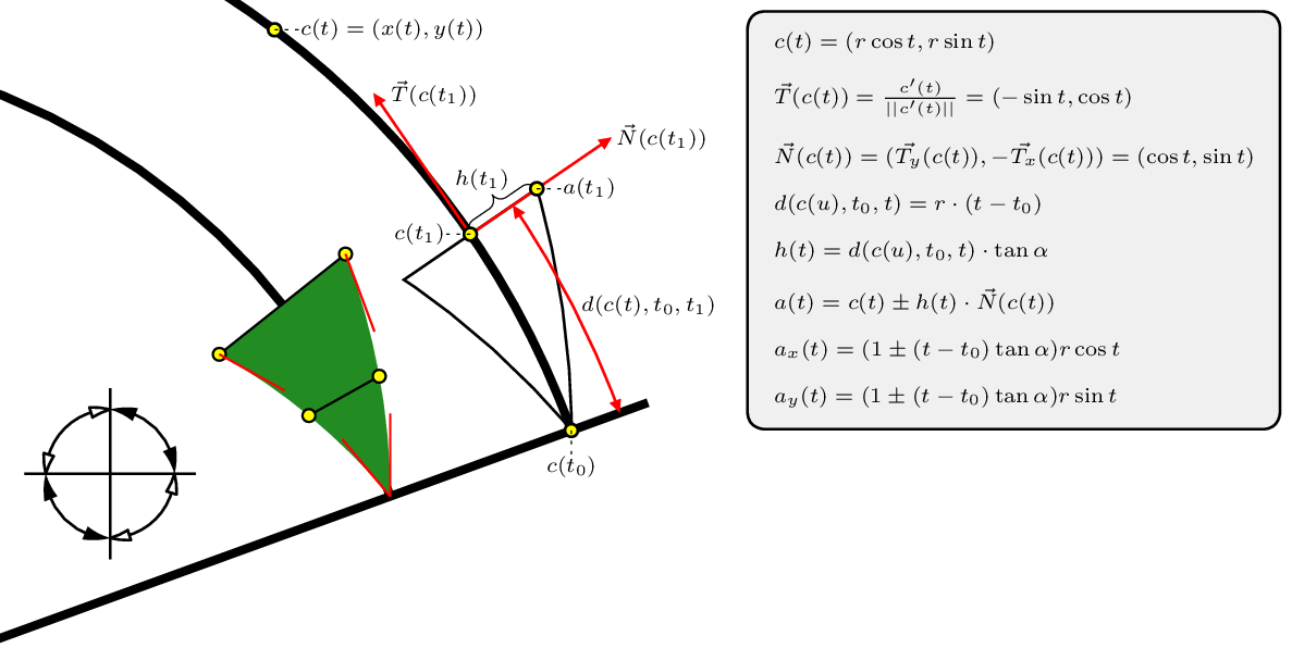
curvedarrow.gle
size 15 7.5

include "shape.gle"

! extra space between rows in LaTeX table (on the right)
begin texpreamble
   \usepackage{tabls}
   \setlength{\tablinesep}{0.3cm}
end texpreamble

! draw tiny dotted lines between point and corresponding label
sub hair_line dx dy
   gsave
   set lwidth 0.0125 lstyle 2
   rline dx dy
   grestore
   rmove dx dy
end sub

! draw a small circle filled yellow
sub yellow_circle x y
   amove x y
   circle 0.075 fill yellow
end sub

! set the opening angle and size of the arrow
sub set_arr_angle_size ang siz
   tan_alpha = tan(torad(ang))
   arr_angle = ang
   arr_size  = siz
end sub

! get the value of "t1" given the arrow length
sub get_delta_theta arrlen
   side = arrlen * cos(torad(arr_angle))
   return todeg(side/r)
end sub

! evaluate a degree 5 polynomial
sub ev5 a5 a4 a3 a2 a1 a0 x
   return a5*x^5 + a4*x^4 + a3*x^3 + a2*x^2 + a1*x + a0
end sub

! evaluate the first derivative of a degree 5 polynomial
sub ev5p a5 a4 a3 a2 a1 a0 x
   return 5*a5*x^4 + 4*a4*x^3 + 3*a3*x^2 + 2*a2*x + a1
end sub

! compute the norm of a given vector
sub norm x1 y1
   return sqrt(x1^2+y1^2)
end sub

! compute the x-coordinate of a point on the arrow side
sub ax t0 t pm
   return (1+pm*(t-t0)*tan_alpha)*r*cos(t)
end sub

! compute the y-coordinate of a point on the arrow side
sub ay t0 t pm
   return (1+pm*(t-t0)*tan_alpha)*r*sin(t)
end sub

! compute the first derivative of the x-coordinate of the arrow side
sub apx t0 t pm
   return r*(-sin(t)+pm*tan_alpha*(cos(t)-t*sin(t)+t0*sin(t)))
end sub

! compute the first derivative of the y-coordinate of the arrow side
sub apy t0 t pm
   return r*(cos(t)+pm*tan_alpha*(sin(t)+t*cos(t)-t0*cos(t)))
end sub

! normalized first derivative of the x-coord of the arrow side
sub apx_norm t0 t pm pm2
   local tx = apx(t0,t,pm2)
   local ty = apy(t0,t,pm2)
   local d = norm(tx,ty)
   return pm*tx/d
end sub

! normalized first derivative of the y-coord of the arrow side
sub apy_norm t0 t pm pm2
   local tx = apx(t0,t,pm2)
   local ty = apy(t0,t,pm2)
   local d = norm(tx,ty)
   return pm*ty/d
end sub

! compute a bezier curve through a given point
! assume two control points at same distance from the end points
sub bezier_slope_pt x0 y0 dx1 dy1 dx2 dy2 x3 y3 xp yp
   local a = xp - x0
   local b = 3*(x0-x3)
   local c = 2*(x3-x0)
   local d = dx1
   local e = dx2 - 2*dx1
   local f = dx1 - dx2
   local g = yp - y0
   local h = 3*(y0-y3)
   local i = 2*(y3-y0)
   local j = dy1
   local k = dy2 - 2*dy1
   local l = dy1 - dy2
   local a5 = c*l - i*f
   local a4 = c*k + b*l - i*e - h*f
   local a3 = c*j + b*k - i*d - h*e
   local a2 = b*j + a*l - h*d - g*f
   local a1 = a*k - g*e
   local a0 = a*j - g*d
   local t  = 0.5
   local tp = 0
   while abs(t-tp) > 1e-6
      tp = t
      t = t - ev5(a5,a4,a3,a2,a1,a0,t)/ev5p(a5,a4,a3,a2,a1,a0,t)
   next
   local aa = (a + b*t^2 + c*t^3)/(d + e*t + f*t^2)/(3*t)
   asetpos x0 y0
   bezier x0+aa*dx1 y0+aa*dy1 x3+aa*dx2 y3+aa*dy2 x3 y3
   return aa
end sub

! draw the curved arrow head
sub curved_arrow_head x0 y0 a1 a2 deco outline
   t0 = torad(a1)
   tm = torad((a1 + a2)/2)
   t1 = torad(a2)
   ! top side (pm = +1)
   local dx11  = apx_norm(t0,t1,-1,+1)
   local dy11  = apy_norm(t0,t1,-1,+1)
   local dx21  = apx_norm(t0,t0,+1,+1)
   local dy21  = apy_norm(t0,t0,+1,+1)
   local x01   = ax(t0,t1,+1) + x0
   local y01   = ay(t0,t1,+1) + y0
   local x31   = ax(t0,t0,+1) + x0
   local y31   = ay(t0,t0,+1) + y0
   local xp1   = ax(t0,tm,+1) + x0
   local yp1   = ay(t0,tm,+1) + y0
   ! bottom side (pm = -1)
   local dx12  = apx_norm(t0,t0,+1,-1)
   local dy12  = apy_norm(t0,t0,+1,-1)
   local dx22  = apx_norm(t0,t1,-1,-1)
   local dy22  = apy_norm(t0,t1,-1,-1)
   local x02   = ax(t0,t0,-1) + x0
   local y02   = ay(t0,t0,-1) + y0
   local x32   = ax(t0,t1,-1) + x0
   local y32   = ay(t0,t1,-1) + y0
   local xp2   = ax(t0,tm,-1) + x0
   local yp2   = ay(t0,tm,-1) + y0
   ! only draw the outline or fill it in green?
   if outline = 1 then
      begin path stroke
         local aa1 = bezier_slope_pt(x01,y01,dx11,dy11,dx21,dy21,x31,y31,xp1,yp1)
         local aa2 = bezier_slope_pt(x02,y02,dx12,dy12,dx22,dy22,x32,y32,xp2,yp2)
         closepath
      end path
   else
      print "dx1 " dx11 " dy1 " dy11 " dx2 " dx21 " dy2 " dy21
      begin path fill forestgreen
         local aa1 = bezier_slope_pt(x01,y01,dx11,dy11,dx21,dy21,x31,y31,xp1,yp1)
         local aa2 = bezier_slope_pt(x02,y02,dx12,dy12,dx22,dy22,x32,y32,xp2,yp2)
         closepath
      end path
   end if
   ! draw decorations?
   if deco = 1 then
      gsave
      set color black lwidth 0.025
      amove x01 y01
      aline x32 y32
      amove xp1 yp1
      aline xp2 yp2
      yellow_circle x01 y01
      yellow_circle xp1 yp1
      yellow_circle x32 y32
      yellow_circle xp2 yp2
      set color red
      amove x01 y01
      aline x01+dx11*aa1 y01+dy11*aa1
      amove x31 y31
      aline x31+dx21*aa1 y31+dy21*aa1
      amove x02 y02
      aline x02+dx12*aa2 y02+dy12*aa2
      amove x32 y32
      aline x32+dx22*aa2 y32+dy22*aa2
      grestore
   end if
   ! name some crucial points on the arrow head
   amove x0+r*cos(torad(a2)) y0+r*sin(torad(a2))
   save tcenter
   rmove -2*sin(torad(a2)) 2*cos(torad(a2))
   save ttangent
   amove x01 y01
   save tnormal
   amove x31 y31
   save btip
end sub

! some general settings
set lwidth 0.1 join mitre
set_arr_angle_size 20 2.75

a1 = 20
r  = +8
x0 = -3
y0 = -1

! draw a line at angle 20 degrees
amove x0 y0
aline x0+(r+3.2)*cos(torad(a1)) y0+(r+3.2)*sin(torad(a1))

! draw the first arc
amove x0 y0
arc r a1 90

! draw the arc's arrow head
a2 = a1+get_delta_theta(2.75)
curved_arrow_head x0 y0 a1 a2 1 0

! draw another arc and arrow head
r = +10.25
set color black
amove x0 y0
arc r a1 90
set lwidth 0.03
a2 = a1+get_delta_theta(2.75)
curved_arrow_head x0 y0 a1 a2 0 1

! draw the math equation of the curve
yellow_circle x0+r*cos(torad(53)) y0+r*sin(torad(53))
hair_line 0.3 0
set just lc arrowsize 0.15 arrowangle 25 hei 0.25
tex "$c(t) = (x(t),y(t))$"

! annotate with the "tangent"
set color red
amove ptx(tcenter)  pty(tcenter)
aline ptx(ttangent) pty(ttangent) arrow end
rmove 0.2 0
set color black
tex "$\vec{T}(c(t_1))$"

nx = ptx(tnormal)-ptx(tcenter)
ny = pty(tnormal)-pty(tcenter)
d  = norm(nx,ny)
nx = nx/d; ny = ny/d

! annotate with the "normal"
set color red
amove ptx(tcenter)  pty(tcenter)
aline ptx(tcenter)+nx*2 pty(tcenter)+ny*2 arrow end
rmove 0.05 0
set color black
tex "$\vec{N}(c(t_1))$"

! annotate with the distance along the arc
set color red
amove x0 y0
d = 0.6
arc r+d a1 a2 arrow both
set color black
amove x0+(r+d)*cos(torad((a1+a2)/2))+0.1 y0+(r+d)*sin(torad((a1+a2)/2))
tex "$d(c(t),t_0,t_1)$"

! annotate with the height
gsave
set lwidth 0.0125 just bc
curly_bracket ptx(tcenter) pty(tcenter) ptx(tnormal) pty(tnormal) 0.12
amove (ptx(tcenter)+ptx(tnormal))/2-0.25 (pty(tcenter)+pty(tnormal))/2+0.25
tex "$h(t_1)$"
grestore

! indicate points t0 and t1 on the arrow head
yellow_circle ptx(btip) pty(btip)
hair_line 0 -0.3
set just tc
tex "$c(t_0)$"
yellow_circle ptx(tcenter) pty(tcenter)
hair_line -0.3 0
set just rc
tex "$c(t_1)$"
yellow_circle ptx(tnormal) pty(tnormal)
hair_line 0.3 0
set just lc
tex "$a(t_1)$"

! add all mathematical equations
set just tr
amove pagewidth()-0.2 pageheight()-0.2
begin box add 0.1 fill rgb255(240,240,240) round 0.2
   begin tex
      \begin{tabular}{l}
      $c(t) = (r\cos{t},r\sin{t})$\\
      $\vec{T}(c(t)) = \frac{c'(t)}{||c'(t)||} = (-\sin{t},\cos{t})$  \\
      $\vec{N}(c(t)) = (\vec{T_y}(c(t)), -\vec{T_x}(c(t))) = (\cos{t},\sin{t})$\\
      $d(c(u),t_0,t) = r\cdot(t-t_0)$\\
      $h(t) = d(c(u),t_0,t)\cdot\tan{\alpha}$\\
      $a(t) = c(t) \pm h(t) \cdot \vec{N}(c(t))$\\
      $a_x(t) = (1 \pm (t-t_0)\tan{\alpha}) r \cos{t}$\\
      $a_y(t) = (1 \pm (t-t_0)\tan{\alpha}) r \sin{t}$\\
      \end{tabular}
   end tex
end box

! test the arrow functions from GLE
set arrowsize 0.3 arrowangle 15
amove 0.25 2
aline 2.25 2
amove 1.25 3
aline 1.25 1
amove 1.25 2
set arrowstyle filled
arc 0.75 0   90  arrow both
arc 0.75 180 270 arrow both
set arrowstyle empty
arc 0.75 90  180 arrow both
arc 0.75 270 0   arrow both
ellipsearrow.gle
ellipsearrow.gle
size 12 6

! Illustrates curved arrows on circle arcs, ellipse arcs, and bezier curves

set lwidth 0.05 arrowangle 18 arrowsize 0.5 arrowstyle empty arrowtip round

amove 6 3
elliptical_arc 5.5 2.5 90  180
elliptical_arc 5.5 2.5 270 360

amove 0  3
aline 12 3
amove 6  0
aline 6  6

set color red
amove 6 3
elliptical_arc 5.5 2.5 0   90  arrow both
elliptical_arc 5.5 2.5 180 270 arrow both

amove 6 3
arc 1.5 90  180
arc 1.5 270 360
set color black arrowstyle filled
arc 1.5 0   90  arrow both
arc 1.5 180 270 arrow both

set color blue
amove 2.5 3
aline 6   1 curve -48 180 2 2
amove 9.5 3
aline 6   5 curve 135 0 2 2

set color black arrowstyle simple
amove 6   5
aline 2.5 3 curve 180 135 2 2 arrow both
amove 6   1
aline 9.5 3 curve 0 -45 2 2 arrow both
ellipses.gle
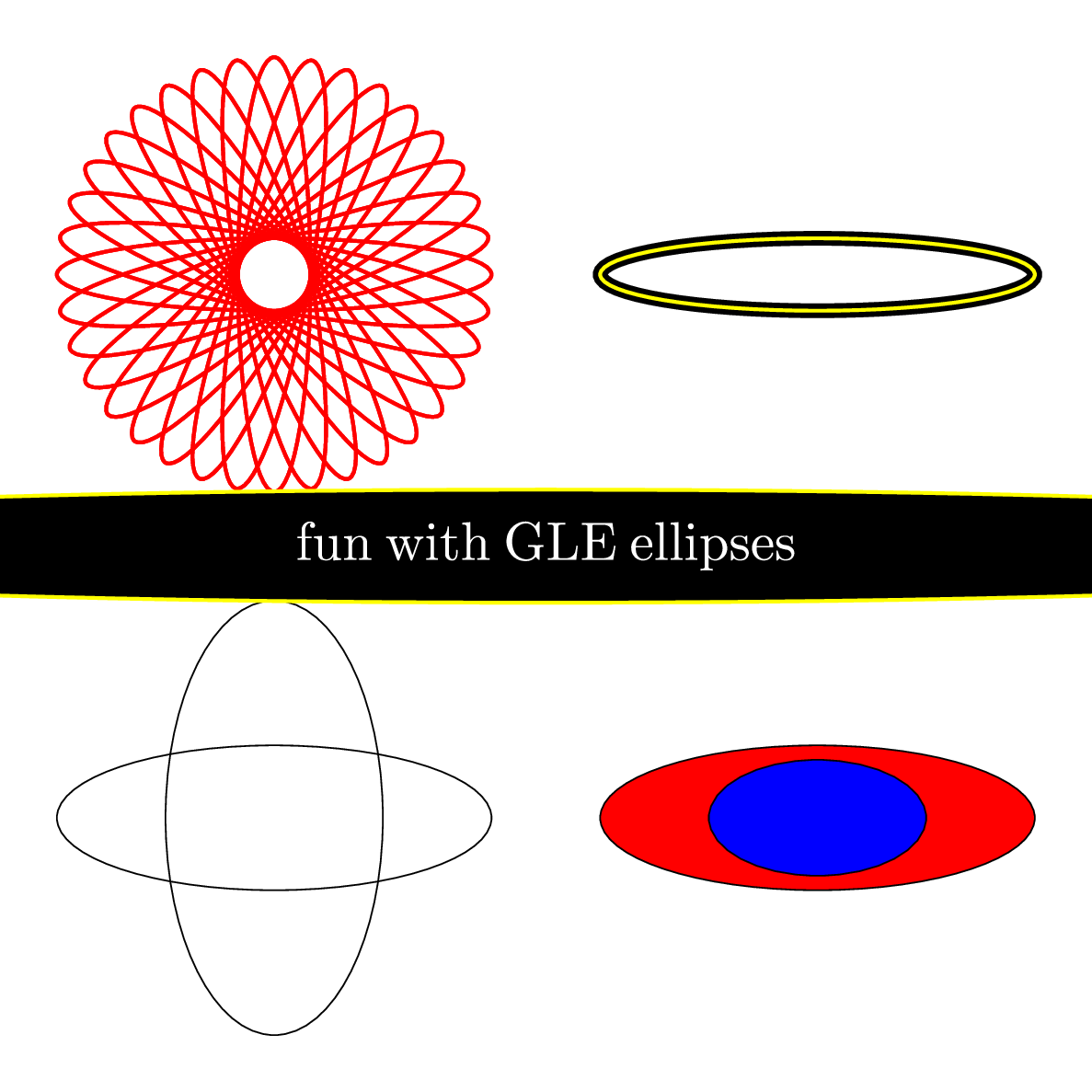
ellipses.gle
!
! ellispes - demo of new ellipse functions
!
size 15 15


amove 15/4 15/4
ellipse 3 1
ellipse 1.5 3

amove 3*15/4 15/4

ellipse 3 1 fill red
ellipse 1.5 0.8 fill blue

set color black
set lwidth 0.2

amove 3*15/4 3*15/4

ellipse 3 0.5
set color yellow
set lwidth 0.05
ellipse 3 0.5

amove 15/4 3*15/4

stp=10
set color red
for i=0 to 360-stp STEP stp
    begin rotate i
    ellipse 3 0.5
    end rotate

next i

set color black
amove 15/2 15/2
set just cc
set font ss
set hei 0.75

txt$="fun with GLE ellipses"
set color YELLOW
ellipse 2.25*TWIDTH(txt$) 1.5*THEIGHT(txt$) fill BLACK
set color white
write txt$
elliptical_arcs.gle
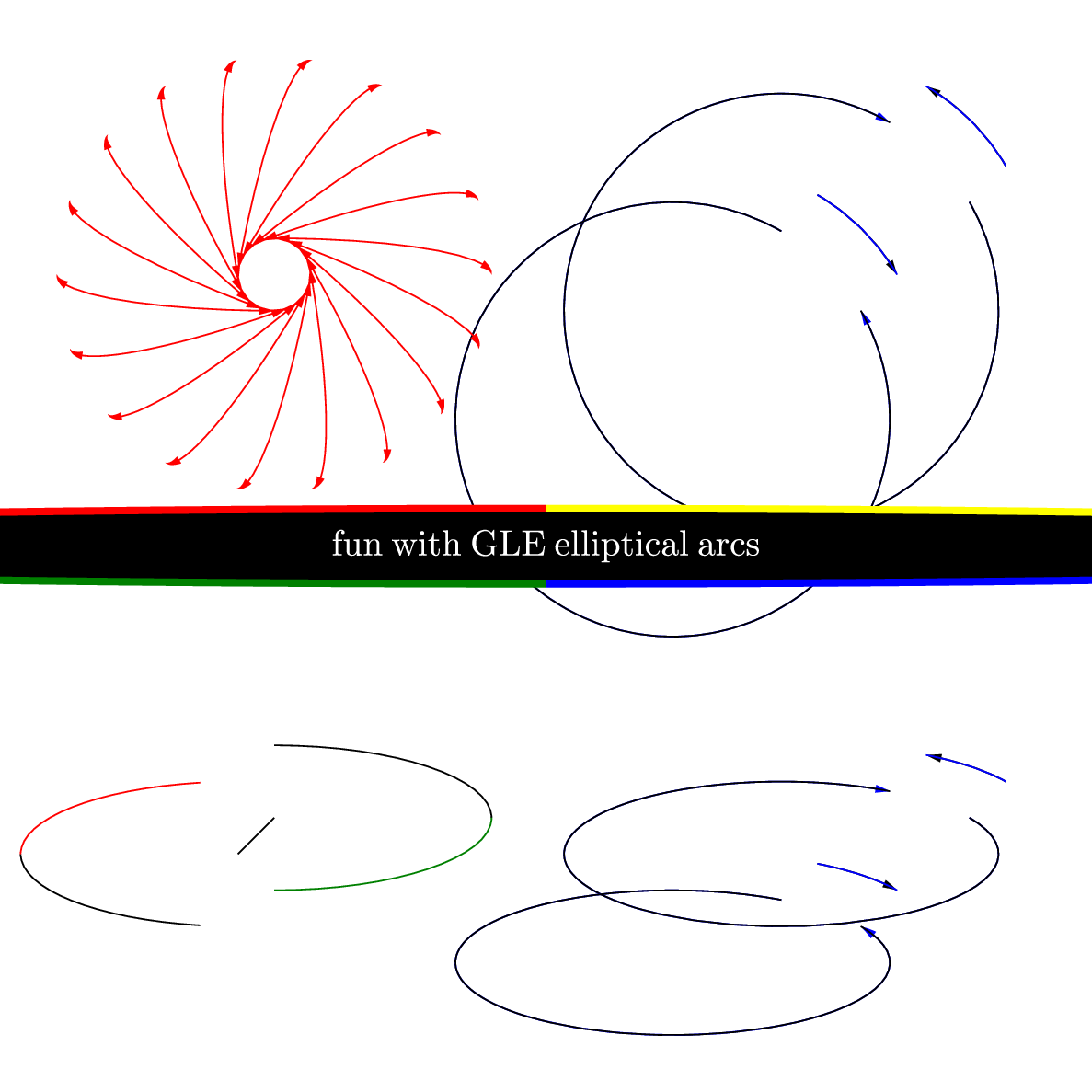
elliptical_arcs.gle
!
! ellispes - demo of new elliptical arc functions with arrows
!
size 15 15


amove 15/4 15/4
elliptical_arc 3 1 0 90
set color GREEN
elliptical_arc 3 1 270 360
set color BLACK
rline -0.5 -0.5

elliptical_arc 3 1 180 260

set color red
elliptical_arc 3 1 100 180


! bugs arrow move current position from center fix it
! elliptical narcs and cricular narcs have arrows backwards

set color black
amove 3*15/4 15/4
elliptical_arc 3 1 30 60 arrow end
set color blue
elliptical_arc 3 1 30 60
rmove -0.5 -0.5
set color blue
elliptical_narc 3 1 30 60 arrow end
set color black
elliptical_narc 3 1 30 60


rmove -1 -1

set color black

elliptical_arc 3 1 30 60 arrow start
set color blue
elliptical_arc 3 1 30 60
rmove -0.5 -0.5
set color blue
elliptical_narc 3 1 30 60 arrow start
set color black
elliptical_narc 3 1 30 60

!elliptical_arc 3 1 100 150 arrow start
!elliptical_arc 3 1 200 270 arrow both


!elliptical_narc 3 1 100 150 arrow start
!elliptical_narc 3 1 200 270 arrow both


amove 3*15/4 3*15/4

arc 3  30 60 arrow end
set color blue
arc 3  30 60
rmove -0.5 -0.5
set color blue
narc 3  30 60 arrow end
set color black
narc 3  30 60


rmove -1 -1

set color black

arc 3  30 60 arrow start
set color blue
arc 3  30 60
rmove -0.5 -0.5
set color blue
narc 3  30 60 arrow start
set color black
narc 3  30 60


amove 15/4 3*15/4

stp=20
set color red
for i=0 to 360-stp STEP stp
    begin rotate i
    elliptical_arc 3 0.5 0 90 arrow both
    end rotate

next i

set color black
amove 15/2 15/2
set just cc
set font ss
set hei 0.5

txt$="fun with GLE elliptical arcs"
ellipse 3.0*TWIDTH(txt$) 1.5*THEIGHT(txt$) fill BLACK
set lwidth 0.1
set color YELLOW
elliptical_arc 3.0*TWIDTH(txt$) 1.5*THEIGHT(txt$) 0 90
set color RED
elliptical_arc 3.0*TWIDTH(txt$) 1.5*THEIGHT(txt$) 90 180
set color GREEN
elliptical_arc 3.0*TWIDTH(txt$) 1.5*THEIGHT(txt$) 180 270
set color BLUE
elliptical_arc 3.0*TWIDTH(txt$) 1.5*THEIGHT(txt$) 270 360

set color white
write txt$
flux_linkage_space_vector_diagram.gle
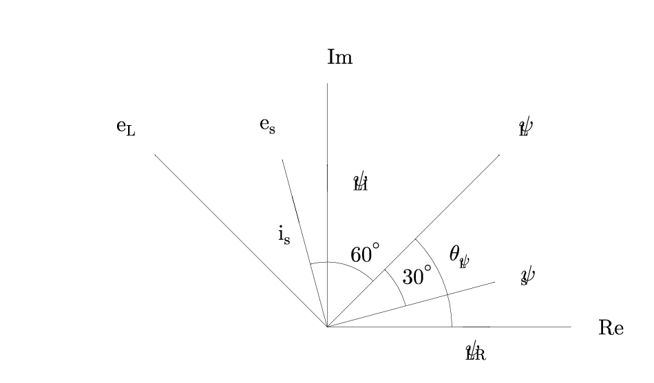
flux_linkage_space_vector_diagram.gle
! Space phasor diagram for flux linkage estimator
size 12 7


! Arc with arrows on both ends
sub arcarrow radius ang1 ang2 fntheight
    arc radius ang1 ang2 arrow end
end sub

begin scale 0.1 0.1

    amove 60 10
    begin origin ! 0,0 now at 50,10 (common point)
        ! Lines with arrows
        ! may need set hei for arrow sizes
        arrow_size = 7
        set hei arrow_size

        ! Real axis
        set lstyle 1
        rline 45 0
        amove 0 0

        ! Imag Axis
        set lstyle 1
        rline 0 45
        amove 0 0

        ! \psi_s
        set lstyle 1
        rline 32*cos(torad(15)) 32*sin(torad(15)) arrow end
        amove 0 0

        ! \psi_L
        set lstyle 1
        rline 45*cos(torad(45)) 45*sin(torad(45)) arrow end
        amove 0 0

        ! e_s
        set lstyle 1
        rline -32*cos(torad(75)) 32*sin(torad(75)) arrow end
        amove 0 0

        ! e_L
        set lstyle 1
        rline -45*cos(torad(45)) 45*sin(torad(45)) arrow end
        amove 0 0

        ! Angle measurements
        @arcarrow 23 0 45 arrow_size
        @arcarrow 15 15 45 arrow_size
        @arcarrow 12 45 105 arrow_size

        ! Arrows on axes
        set lstyle 1
        amove 25 0
        rline 5 0 arrow end
        amove 0 25
        rline 0 5 arrow end
        amove -20*cos(torad(75)) 20*sin(torad(75))
        rline -5*cos(torad(75)) 5*sin(torad(75)) arrow end
        set lstyle 1

        ! Text
        set just CL
        set hei 4
        amove 50 0
        text Re
        amove 0 50
        text Im

        amove 37*cos(torad(15)) 37*sin(torad(15))
        text \psi_s

        amove 26*cos(torad(30)) 26*sin(torad(30))
        text \theta_{\psi_L}

        amove 50*cos(torad(45)) 50*sin(torad(45))
        set just BL
        text \psi_L

        amove 27.5*cos(torad(-5)) 27.5*sin(torad(-5))
        set just TC
        text \psi_{LR}

        amove 27.5*cos(torad(80)) 27.5*sin(torad(80))
        set just CL
        text \psi_{LI}

        amove  -20*cos(torad(70)) 20*sin(torad(70))
        set just TR
        text i_s

        amove -37*cos(torad(75)) 37*sin(torad(75))
        set just BR
        text e_s

        amove -50*cos(torad(45)) 50*sin(torad(45))
        set just BR
        text e_L

        amove 16*cos(torad(30)) 16*sin(torad(30))
        set just BL
        text 30^{\circ}

        amove 14*cos(torad(60)) 14*sin(torad(60))
        set just BC
        text 60^{\circ}

    end origin
end scale
house.gle
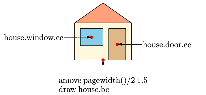
house.gle
size 9 4.1

set font psh

sub red_bullet
   ! draw a red bullet
   gsave
   set color red fill red
   circle 0.06
   grestore
end sub

begin object house
   ! draw a house with a named door and window
   set join round
   ! draw the roof
   begin path stroke fill lightsalmon
      amove 0 1.625
      aline 1.25 2.5
      aline 2.5 1.625
      closepath
   end path
   ! draw the brick wall
   amove 0 0
   box 2.5 1.625 fill cornsilk
   ! draw the door
   amove 1.5 0
   box 0.75 1.375 fill burlywood name door
   ! draw the window
   amove 0.25 0.625
   box 1 0.75 fill skyblue name window
end object

! draw the house
amove pagewidth()/2 1.5
draw house.bc
red_bullet

! mark the door and window with a red bullet
move house.door.cc
red_bullet
move house.window.cc
red_bullet

! draw the labels
set just bc
amove pagewidth()/2 0.1
begin name drawcmd add 0.05
   begin text
      amove pagewidth()/2 1.5
      draw house.bc
   end text
end name

set just lc
amove pointx(house.rc)+0.5 pointy(house.door.cc)
begin name doorlabel add 0.05
   write "house.door.cc"
end name

set just rc
amove pointx(house.lc)-0.5 pointy(house.window.cc)
begin name windowlabel add 0.05
   write "house.window.cc"
end name

! draw the arrows
join drawcmd.tc -> house.bc
join windowlabel.rc -> house.window.cc
join doorlabel.lc -> house.door.cc
logo.gle
![]()
logo.gle
!
! GLE logo for web page
! by: V.P. LaBella vlabella@albany.edu
!
size 12 6

set font psagb

dx = 12; dy = 6; boxw = dx/7; boxh = dy

amove 0 0
set color white
box dx dy

sub draw_box clr$
    gsave
    set color clr$
    box boxw boxh fill clr$
    grestore
end sub

amove dx/2 dy/2+0.5
set just cc
begin clip          ! Save default clipping region
    begin path clip ! Set up the clipping region
        set hei 6.0
        text GLE
    end path
    amove 0 0
    draw_box red
    rmove boxw 0
    draw_box orange
    rmove boxw 0
    draw_box yellow
    rmove boxw 0
    draw_box lime
    rmove boxw 0
    draw_box blue
    rmove boxw 0
    draw_box navy
    rmove boxw 0
    draw_box violet
    rmove boxw 0
    gsave
    set hei 0.67
    delta=0.8
    amove dx/2 dy-delta
    set color black
    for i=1 to 10
        write "Professional Graphics Language"
        rmove 0.0 -delta
    next i
    grestore
end clip

!
! lower name
!
set just cc
set hei 0.669
set color black
amove dx/2 0.5
write "Professional Graphics Language"

!
! version number
!
amove 9.4 1.8
set hei 1.0
set just bl
set color gray40
write "v4.0"
mirrors.gle
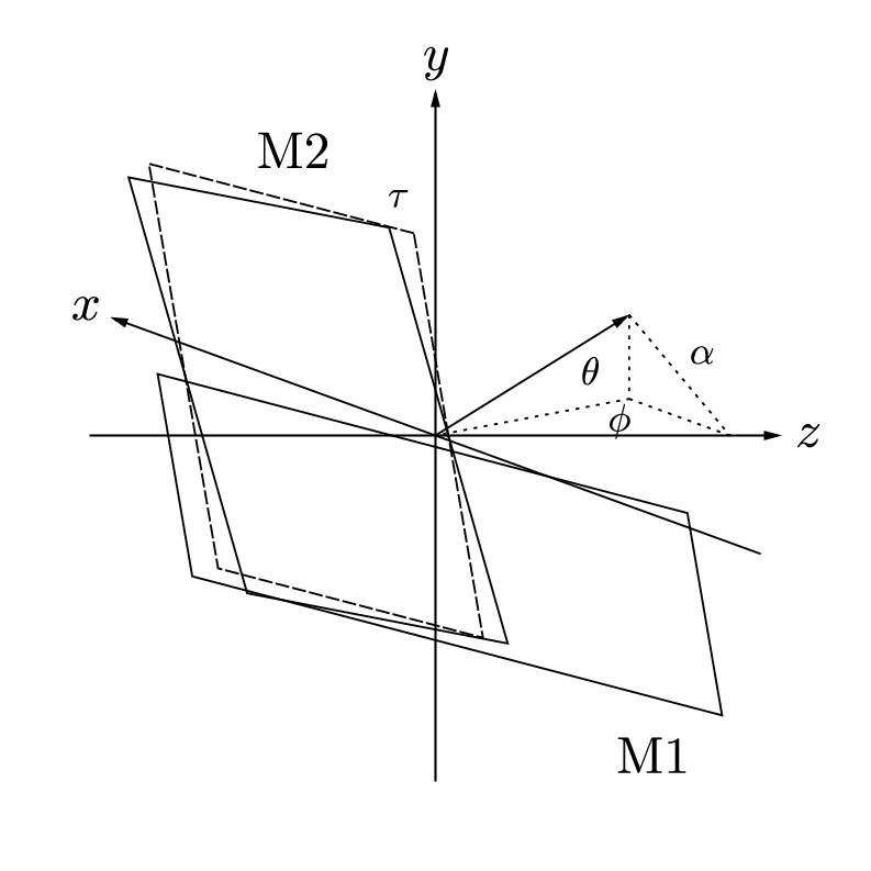
mirrors.gle
size 10 10
set font texcmmi

!  There are two problems here. First, given the appropriate dimensions
!  and angle, we need to determine the actual positions of the
!  important points. It might also be handy to calculate the other
!  angles, although I doubt I'd use them since I'm principally
!  concerned with obtaining a general diagram. I then need to determine
!  the projected values of these points for a 2d representation.

!   Firstly, then, I need to work out the actual points. I'll use two
!   mirrors of dimensions Lx2L. One has a horizontal edge, the other a
!   vertical one. Inclinations are given by theta and phi, and at some
!   point later I then need to work out tau, I think.

! Angle of orthonormal projection of axis out of screen
proj_angle=-70

! Inclination to horizontal plane
theta_deg=15
theta=torad(theta_deg)

! Rotation about vertical (y) axis
phi_deg=-20
phi=torad(phi_deg)

! "Yaw"
! This rotation about the mirror normal (initially the z-axis) ensures
! that the long edge of M2 runs in a plane parallel to the y-z
! plane. This means that a beam along the z-axis will always percieve
! this edge as vertical.
tau=atan(sin(theta)*tan(phi))

! Mirror dimension (Lx2L)
L=2.5
! Axis length
axis_l=4
! Mirror separation
d=0.5

!-------------------------------------------
! Horizontal and vertical vector for mirror M1
h1_x=1
h1_y=0
h1_z=0
v1_x=0
v1_y=1
v1_z=0

! Horizontal and vertical vector for mirror M2
h2_x=1
h2_y=0
h2_z=0
v2_x=0
v2_y=1
v2_z=0

! Mirror normal unit vector
n_x=0
n_y=0
n_z=-1

!   Rotations should be applied in the order theta (about x), phi
!   (about y), and tau is either first or last, depending on how it is
!   worked out. (Actually, do tau first)

sin_phi = sin(phi)
cos_phi = cos(phi)
sin_theta = sin(theta)
cos_theta = cos(theta)

! Rotate about z-axis
sub rotate_tau x y z
x_new=x*cos(tau)-y*sin(tau)
y_new=x*sin(tau)+y*cos(tau)
z_new=z
end sub

! Rotate about x-axis
sub rotate_theta x y z
x_new=x
y_new=z*sin_theta+y*cos_theta
z_new=z*cos_theta-y*sin_theta
end sub

! Rotate about y-axis
sub rotate_phi x y z
x_new=x*cos_phi-z*sin_phi
y_new=y
z_new=x*sin_phi+z*cos_phi
end sub

! 1) Rotate M2 vectors about z

@rotate_tau h2_x h2_y h2_z
h2_x=x_new
h2_y=y_new
h2_z=z_new

@rotate_tau v2_x v2_y v2_z
v2_x=x_new
v2_y=y_new
v2_z=z_new

! 2) Rotate both mirrors and normal about x

@rotate_theta h1_x h1_y h1_z
h1_x=x_new
h1_y=y_new
h1_z=z_new
@rotate_theta v1_x v1_y v1_z
v1_x=x_new
v1_y=y_new
v1_z=z_new

@rotate_theta h2_x h2_y h2_z
h2_x=x_new
h2_y=y_new
h2_z=z_new
@rotate_theta v2_x v2_y v2_z
v2_x=x_new
v2_y=y_new
v2_z=z_new

@rotate_theta n_x n_y n_z
n_x=x_new
n_y=y_new
n_z=z_new

! 3) Rotate both mirrors and normal about y

@rotate_phi h1_x h1_y h1_z
h1_x=x_new
h1_y=y_new
h1_z=z_new
@rotate_phi v1_x v1_y v1_z
v1_x=x_new
v1_y=y_new
v1_z=z_new

@rotate_phi h2_x h2_y h2_z
h2_x=x_new
h2_y=y_new
h2_z=z_new
@rotate_phi v2_x v2_y v2_z
v2_x=x_new
v2_y=y_new
v2_z=z_new

@rotate_phi n_x n_y n_z
n_x=x_new
n_y=y_new
n_z=z_new

!    Need to produce an othographic projection of my diagram.
!    To achieve this map:
!    z -> 0
!    y -> y + Bx
!    x -> z + Ax
!    Where A and B could be defined by some angle and scaling factor.

A=1*sin(torad(proj_angle))
B=1*cos(torad(proj_angle))

! This subroutine takes in the 3d co-ordinates and gives the projected
! 2d co-ords as x_render and y_render - use these immediately as they
! are liable to change.
x_render=0
y_render=0
sub render x y z
x_render=z+A*x
y_render=y+B*x
end sub

! amove, aline, rmore, rline in projected space:
sub pamove x y z
amove z+A*x y+B*x
end sub

sub prmove x y z
rmove z+A*x y+B*x
end sub

sub paline x y z
aline z+A*x y+B*x
end sub

sub prline x y z
rline z+A*x y+B*x
end sub

sub paline_arrow x y z
aline z+A*x y+B*x arrow end
end sub

sub prline_arrow x y z
rline z+A*x y+B*x arrow end
end sub

! Now let's start drawing!

! Work out unit normal vectors for later
@render n_x n_y n_z
n_rx=x_render
n_ry=y_render

amove 5 5
begin origin

!------------------------------------
! First of all, let's do the axes

set hei 0.6

! x-axis
@pamove -axis_l 0 0
@paline_arrow axis_l 0 0
@prmove 0.3 0 0
set just cc
text x

! y-axis
@pamove 0 -axis_l 0
@paline_arrow 0 axis_l 0
@prmove 0 0.3 0
set just cc
text y

! z-axis
@pamove 0 0 -axis_l
@paline_arrow 0 0 axis_l
@prmove 0 0 0.3
set just cc
text z

!-----------------------------------

!Mirror M1

amove 0 0
! Given that I've got the unit vector I could even separate the two
! mirrors by a multiple of this distance.
rmove 0.5*d*n_rx 0.5*d*n_ry
@prline L*h1_x L*h1_y L*h1_z
@prline -L*v1_x -L*v1_y -L*v1_z
@prline -2*L*h1_x -2*L*h1_y -2*L*h1_z
@prline L*v1_x L*v1_y L*v1_z
@prline L*h1_x L*h1_y L*h1_z
! Label
@prmove -0.7*L*h1_x -0.7*L*h1_y -0.7*L*h1_z
@prmove -1.3*L*v1_x -1.3*L*v1_y -1.3*L*v1_z
gsave
set font texcmr
text M1
grestore

!Mirror M2 - without yaw
set lstyle 3
amove 0 0
rmove -0.5*d*n_rx -0.5*dL*n_ry
@prline L*v1_x L*v1_y L*v1_z
gsave
@prmove 0.05*L*h1_x 0.15*L*v1_y 0.15*L*v1_z
set hei 0.45
text \tau
grestore
@prline L*h1_x L*h1_y L*h1_z
@prline -2*L*v1_x -2*L*v1_y -2*L*v1_z
@prline -L*h1_x -L*h1_y -L*h1_z
@prline L*v1_x L*v1_y L*v1_z

! With yaw
set lstyle 0
amove 0 0
rmove -0.5*d*n_rx -0.5*dL*n_ry
@prline L*v2_x L*v2_y L*v2_z
@prline L*h2_x L*h2_y L*h2_z
@prline -2*L*v2_x -2*L*v2_y -2*L*v2_z
@prline -L*h2_x -L*h2_y -L*h2_z
@prline L*v2_x L*v2_y L*v2_z
! Label
@prmove 0.3*L*h2_x 0.3*L*h2_y 0.3*L*h2_z
@prmove 1.3*L*v2_x 1.3*L*v2_y 1.3*L*v2_z
gsave
set font texcmr
text M2
grestore

! Normal vector
set lstyle 0
amove 0 0
@paline_arrow -1.5*L*n_x -1.5*L*n_y -1.5*L*n_z
! Show projections onto horizontal plane, and x, y and z axes
set lstyle 2
!gsave
!@paline 0 -1.5*L*n_y 0
!grestore
gsave
@paline 0 0 -1.5*L*n_z
@prmove -L*n_x -L*n_y -0.2*L*n_z
set hei 0.45
text \alpha
grestore
gsave
@prmove 0 1*L*n_y 0.2*L*n_z
set hei 0.45
text \theta
@prmove 0 0.9*L*n_y -0.15*L*n_z
text \phi
grestore
@paline -1.5*L*n_x 0 -1.5*L*n_z
gsave
aline 0 0
grestore
!gsave
!@paline -1.5*L*n_x 0 0
!grestore
gsave
@paline 0 0 -1.5*L*n_z
grestore
end origin

! Possible improvements
! 1) Need to clean-up axis label positions (only normal)
! 2) Shade in mirrors? Might need extra heuristics for overlapping
!    regions
! 3) Label angles phi, theta, tau, alpha and distance d
perceptron.gle
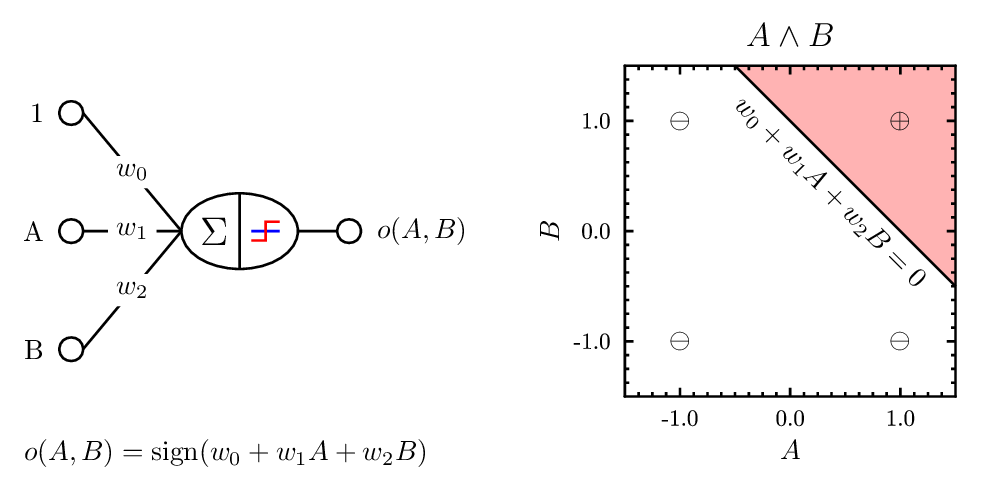
perceptron.gle
size 12.5 6

set lwidth 0.03
graphsiz = 6

include "shape.gle"
include "ellipse.gle"

! draw graph on the right
amove pagewidth()-graphsiz+0.5 0.1
begin graph
   nobox
   size graphsiz graphsiz
   xaxis min -1.5 max 1.5 dticks 0.25
   yaxis min -1.5 max 1.5 dticks 0.25
   xplaces -1 0 1
   yplaces -1 0 1
   xtitle "\tex{$A$}"
   ytitle "\tex{$B$}"
   title "\tex{$A \land B$}"
   let d1 = 1-x from -1 to 1.5 step 0.5
   d1 line
   fill d1,x2 color CVTRGB(1,0.7,0.7)
end graph

! draw labeled instances on the graph
set just cc
amove xg(-1) yg(-1)
tex "$\ominus$"
amove xg(1) yg(-1)
tex "$\ominus$"
amove xg(-1) yg(1)
tex "$\ominus$"
amove xg(1) yg(1)
tex "$\oplus$"

! draw equation representing decision surface
set just tc
amove xg(0.5)-0.1 yg(0.5)-0.1
begin rotate -45
   tex "$w_0 + w_1 A + w_2 B = 0$"
end rotate

! draw sign function for perceptron node
sub drawsign dx
   set color blue
   rline dx 0
   rmove -dx -dx/3
   set color red
   rline dx/2 0
   rline 0 2*dx/3
   rline dx/2 0
   set color black
end sub

! draw percepton internal node (sum + sign function)
set just lc
amove 2.5 yg(0)
begin name perceptron
   tex "{\Large $\Sigma$}" name sum
   amove pointx(sum.rc)+0.3 pointy(sum.rc)
   drawsign width(sum)
end name

! draw ellipse around internal node
set_ellipse_c 0.65
ellipse_obj perceptron ell
amove pointx(ell.tc) pointy(ell.tc)
aline pointx(ell.bc) pointy(ell.bc)

! draw input node, label and weight
sub drawinode idx name$ wi$
   r = 0.15
   xdel = 1.25
   ydel = 1.5
   amove pointx(ell.lc) pointy(ell.lc)
   rline -xdel idx*ydel
   rmove -r 0
   circle r
   rmove -r-0.2 0
   set just rc
   tex name$ name input
   set just cc
   amove pointx(ell.lc)-xdel/2 pointy(ell.lc)+idx*ydel/2
   begin box add 0.1 fill white nobox
      tex wi$
   end box
end sub

! draw output node and label
sub drawonode idx name$
   r = 0.15
   xdel = 0.5
   amove pointx(ell.rc) pointy(ell.rc)
   rline xdel 0
   rmove r 0
   circle r
   rmove r+0.2 0
   set just lc
   tex name$
end sub

! draw the input and output nodes
drawinode 1  "1" "$w_0$"
drawinode 0  "A" "$w_1$"
drawinode -1 "B" "$w_2$"
drawonode 0  "$o(A,B)$"

! draw the function implemented by the perceptron
set just bl
amove pointx(input.lc) 0.1
tex "$o(A,B) = \mathrm{sign}(w_0 + w_1 A + w_2 B)$"
playtennis_dt.gle
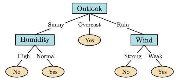
playtennis_dt.gle
size 7.5 3.35

include "tree.gle"

set_ellipse_c 0.5
set_leaf_ellipse_size_str "Yes"

set fill wheat

def_leaf_ellipse "Yes"  "ly"
def_leaf_ellipse "No"   "ln"

set fill powderblue

def_binary_node "Humidity" "High"   "Normal" "ln" "ly" "n1"
def_binary_node "Wind"     "Strong" "Weak"   "ln" "ly" "n2"

def_tertiary_node "Outlook" "Sunny" "Overcast" "Rain" "n1" "ly" "n2" "root"

amove pagewidth()/2 pageheight()-0.1
draw "root.tc"
protract.gle
protract.gle
! A do-it-yourself protractor for GLE
! S.J. Blundell    distributed under GPL
! sjb@ermine.ox.ac.uk      09/08/00

size 18 18
set font plsr hei 0.4

a=8; b=0.3; c=1; d=0.65; f=6; g=6

amove 9 9
begin origin

for i=0 to 359
    begin rotate i
        amove 0 a
        rline 0 -b
    end rotate
next i

set color blue
for i=0 to 350 step 10
    begin rotate i
        amove 0 a
        rline 0 -c
        if i>0 then
            rmove -0.2 -0.5
        else
            rmove -0.1 -0.5
        end if
        write i
    end rotate
next i

set color green
for i=5 to 355 step 10
    begin rotate i
        amove 0 a
        rline 0 -d
    end rotate
next i

set color red
for i=0 to 350 step 10
    begin rotate i
        amove 0 0
        aline 0 g
    end rotate
next i

set color black
amove 0 0
circle 0.3
amove -f 0
aline f 0
amove 0 -f
aline 0 f
amove 0 0

end origin
qgle_keyboard.gle
qgle_keyboard.gle
! QGLE/AutoCAD Keyboard layout

! CONFIGURATION:
keys$ = "QGLE" ! AutoCAD or QGLE
tbh = 2 ! The height of the text box in centimetres
boxsize = 1.9 ! The width of a single function key
boxheight = 2 ! The height of a single function key
lb = 1 ! The left border
rb = 0.5 ! The right border
bb = 0.5 ! The bottom border
tb = 0 ! The top border
mb = 1.025 ! The border between f4 & f5

! Everything else is automatic, so nothing
! needs to be changed from here on (unless you want
! to define keys for a different program.

! Set up the QGLE keys
f1$ = "ABOUT"
f2$ = ""
f3$ = "OSNAP"
f4$ = ""
f5$ = ""
f6$ = "COORD"
f7$ = "GRID"
f8$ = "ORTHO"
f9$ = "SNAP"
f10$ = "POLAR"
f11$ = ""
f12$ = ""

! If we're doing an AutoCAD layout, then
! change the keys that differ
if keys$ = "AutoCAD" then
    f1$ = "HELP"
    f2$ = "TEXTSCR"
    f4$ = "TABLET"
    f5$ = "ISOPLANE"
    f11$ = "OTRACK"
end if

! Page size (4.5 by 26.35):
size bb+boxheight+tbh+tb lb+3*4*boxsize+2*mb+rb

! Create a box for the key text
sub fblock f$
    box boxsize tbh
    rmove boxsize/2 boxheight/2
    write f$
    rmove boxsize/2 -boxheight/2
end sub

! Rotate the page so that it fits
! on a portrait A4 sheet
amove pagewidth()/2 pagewidth()/2
begin rotate 90
    ! Draw the outside box
    amove 0 0
    rline pageheight() 0
    rline 0 pagewidth()
    rline -pageheight() 0
    rline 0 -pagewidth()
    ! Now back at 0 0

    set just cc

    ! Draw the F1-F4 boxes
    amove lb bb
    box boxsize*4 boxheight
    rmove 0 boxheight
    fblock f1$
    fblock f2$
    fblock f3$
    fblock f4$

    ! Draw the F5-F8 boxes
    rmove mb -boxheight
    box boxsize*4 boxheight
    rmove 0 boxheight
    fblock f5$
    fblock f6$
    fblock f7$
    fblock f8$

    ! Draw the F9-F12 boxes
    rmove mb -boxheight
    box boxsize*4 boxheight
    rmove 0 boxheight
    fblock f9$
    fblock f10$
    fblock f11$
    fblock f12$
end rotate
regrmodel.gle
regrmodel.gle
size 5 3.1

! A discussion of this diagram can be found in:
! "Pattern Recognition and Machine Learning" by Christopher M. Bishop

include "shape.gle"

! draw noise variance parameter
amove 0.9 1
set color red fill red
labeled_circle "$\sigma^2$" 0.05 langle 180 name "sigma"

! draw center plate
begin box add 0.2 round 0.2
  ! draw t_n node
   rmove 1.5 0
   set fill thistle
   labeled_circle "$t_n$" 0.35 lradius 0.05 langle 240 name "tn"
   ! draw label "N" on plate
   gsave
   set just tl color black
   pmove 0.6 -45
   tex "$N$"
   grestore
   ! draw x_n node
   rmove 0 1.5
   set fill red
   labeled_circle "$x_n$" 0.05 langle 90 name "xn"
   set color purple
end box

! draw omega node
rmove 1.75 -1.5
set fill thistle color red
labeled_circle "$w$" 0.35 langle 45 name "w"

! draw alpha node
rmove 0 1.5
set fill red
labeled_circle "$\alpha$" 0.05 langle 90 name "alpha"

! connect with arrows
join sigma -> tn
join w -> tn
join alpha -> w
join xn -> tn
shapes-ft.gle
shapes-ft.gle
! Examples of basic shapes.
! Author: Francois Tonneau

! As usual, we start by defining the width and height of the drawing area:

size 10 7.5

! We define the line width for drawing to be 0.03 cm:

set lwidth 0.03

! GLE accepts variables of two types: floating point (i.e., numeric) and string.
! Here we define two numeric variables: 'dist' will be the horizontal distance
! between two shapes; 'adj' will be a small adjustment needed to position some
! of the shapes correctly.

dist = 2
adj = 0.5

set color brown

! For our top row we draw four shapes with standard GLE commands. 'amove' is
! an absolute move, whereas 'rmove' is a move relative to current position. The
! 'just' (or 'justify') parameter to 'box' is assigned value 'cc' to center the
! object on the current position. Possible values for 'just' are:

! tl    tc    tr
! cl    cc    cr
! bl    bc    br

! where t = top, c = center, b = bottom, l = left, r = right.

amove 2 6
box 1 1 just cc
rmove dist 0
box 1 1 just cc round 0.25
rmove dist 0
circle 0.5
rmove dist 0
ellipse 0.55 0.45

! The bottom three rows will rely on shape commands that are not part of the
! standard GLE language, but are defined in a library called 'shape.gle'. (It
! should be available on your system if GLE was installed correctly.) We write
! 'include shape.gle' to be able to use this library:

include shape.gle

! The drawing commands in shape.gle rely on absolute moves, so to draw each of
! the following shapes at its correct place we must use the current position
! as origin. This is done by using 'begin origin ... end origin' blocks:

amove 1.5 4
begin origin
    triangle 1 1
end origin
rmove dist+adj adj
begin origin
    hexagon 1.1 1.1
end origin
rmove dist 0
begin origin
    rhomb 1.1 1.1
end origin
rmove dist 0
begin origin
    disk
end origin

! We draw another row of shapes:

amove 2 3
begin origin
    plus 1 1
end origin
rmove dist 0
begin origin
    cross 0.8 0.8
end origin
rmove dist 0
begin origin
    big_arrow_ud
end origin
rmove dist 0
begin origin
    big_arrow_lr 1.2 0.8
end origin

! And another row:

amove 2 1.5
begin origin
    big_arrow_up
end origin
rmove dist 0
begin origin
    big_arrow_down
end origin
rmove dist 0
begin origin
    big_arrow_left
end origin
rmove dist 0
begin origin
    big_arrow_right
end origin

! Done. In this script we have used variables, the 'include' command, absolute
! moves, relative moves, and 'begin origin ... end origin' blocks.
wulfnet.gle
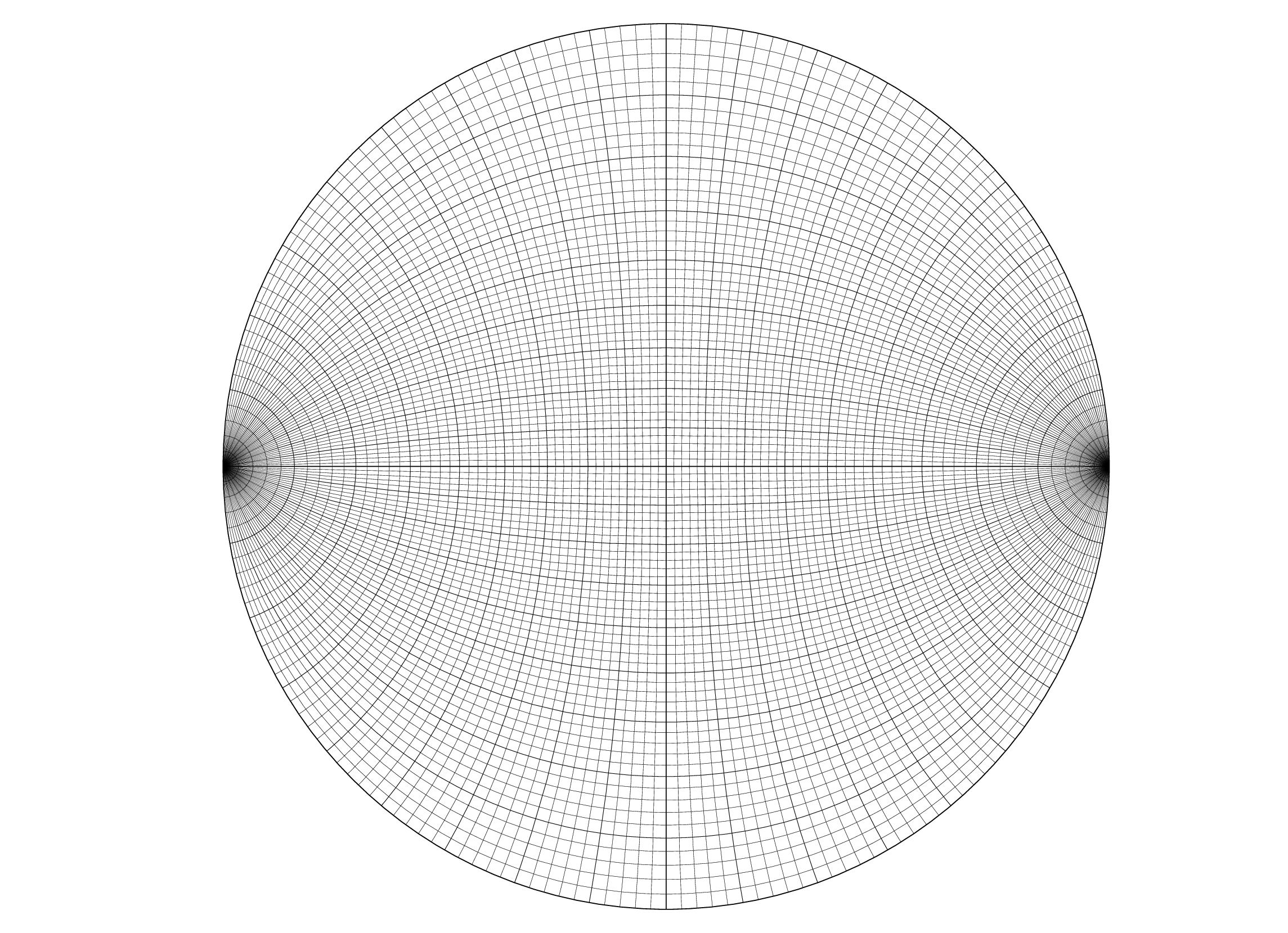
wulfnet.gle
! This example was provided by Ole Göbel

size 29 21

rp = 10                                            ! radius of primitive, only value that needs to be changed to blow up
f = pi/180                                         ! or shrink the entire net
thinl = 0.005                                      ! lwidth of thin lines
thickl = 0.01                                      ! lwidth of thick lines

!drawing primitive and central cross
set lwidth .02
amove 15 10.5
circle rp
rmove 0 -rp
rline 0 2*rp
rmove -rp -rp
rline 2*rp 0
rmove -rp 0

!drawing small circles around east pole
for ang=2 to 88 step 2                             ! defining the grid of small circles
   set lwidth thinl                                ! ang must not become 0 nor 90!
   ang2=180-ang
   r1=rp*sin(ang*f)/(1+cos(ang*f))
   r2=rp*sin(ang2*f)/(1+cos(ang2*f))
   om=(r1+r2)/2
   r=r2-om
   rmove om 0
   if ang/10=int(ang/10) then
      set lwidth thickl                            ! drawing every small circle fatter with: angular
   end if                                          ! distance to east pole = n*10deg
   arc r 180-ang 180+ang
   rmove -om 0
next ang

!drawing small circles around west pole
for ang=2 to 88 step 2                             ! defining the grid of small circles
   set lwidth thinl                                ! ang must not become 0 nor 90!
   ang2=180-ang
   r1=rp*sin(ang*f)/(1+cos(ang*f))
   r2=rp*sin(ang2*f)/(1+cos(ang2*f))
   om=(r1+r2)/2
   r=r2-om
   rmove -om 0
   if ang/10=int(ang/10) then
      set lwidth thickl                            ! drawing every small circle fatter with: angular
   end if                                          ! distance to west pole = n*10deg
   arc r -ang ang
   rmove om 0
next ang

!drawing great circles in northern hemisphere
for ang=2 to 88 step 2                             ! defining the grid of great circles
   set lwidth thinl                                ! ang must not become 0 nor 90!
   ang2=180-ang
   r1=rp*sin(ang*f)/(1+cos(ang*f))
   r2=rp*sin(ang2*f)/(1+cos(ang2*f))
   om=(r2-r1)/2
   r=r2-om
   rmove 0 -om
   if ang/10=int(ang/10) then
      set lwidth thickl                            ! drawing every small circle fatter with: angular
   end if                                          ! distance to primitive = n*10deg
   arc r 90-ang 90+ang
   rmove 0 om
next ang

!drawing great circles in southern hemisphere
for ang=2 to 88 step 2                             ! defining the grid of great circles
   set lwidth thinl                                ! ang must not become 0 nor 90!
   ang2=180-ang
   r1=rp*sin(ang*f)/(1+cos(ang*f))
   r2=rp*sin(ang2*f)/(1+cos(ang2*f))
   om=(r2-r1)/2
   r=r2-om
   rmove 0 om
   if ang/10=int(ang/10) then
      set lwidth thickl                            ! drawing every small circle fatter with: angular
   end if                                          ! distance to primitive = n*10deg
   arc r 270-ang 270+ang
   rmove 0 -om
next ang