Electronic Circuits
None
circuit1.gle
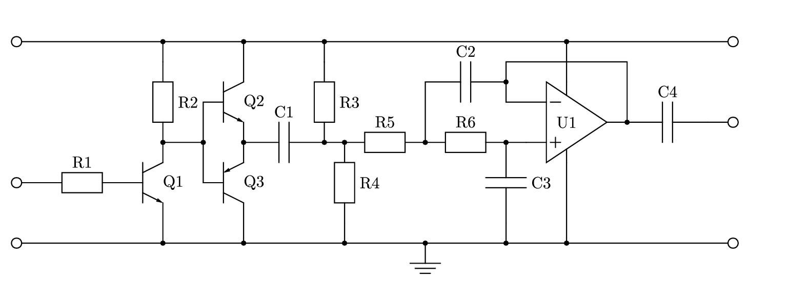
circuit1.gle
! Example circuit with electronics.gle

size 20 7.5

include "electronics.gle"

begin scale 0.5 0.5
   set lwidth 0.05 cap round
   termrad = 0.25
   amove 1 3
   rmove -termrad 0
   circle termrad
   rmove termrad 0
   rline 35 0
   rmove termrad 0
   circle termrad
   amove 1 6
   rmove -termrad 0
   circle termrad
   rmove termrad 0
   rline 1 0
   @resistor_h "R1"
   @npn_bjt "Q1"
   rmove 2 -1
   rline 0 -2
   @connection
   rmove 0 4
   rline 0 1
   @connection
   rmove 0 5
   @connection
   rline 0 -1
   @resistor_v "R2"
   rline 2 0
   @connection
   rline 0 2
   @npn_bjt "Q2"
   rmove 0 -2
   rline 0 -2
   @pnp_bjt "Q3"
   rmove 2 -1
   rline 0 -2
   @connection
   rmove 0 4
   rline 0 2
   rmove 0 2
   rline 0 2
   @connection
   rmove 0 -5
   @connection
   @capacitor_h "C1"
   rmove 0 5
   @connection
   rline 0 -1
   @resistor_v "R3"
   @connection
   rline 1 0
   @connection
   resistor_v "R4"
   rline 0 -1
   @connection
   rmove 0 5
   @resistor_h "R5"
   @connection
   gsave
   @resistor_h "R6"
   @connection
   rline 1 0
   rmove -1 0
   @capacitor_v "C3"
   rline 0 -1
   @connection
   grestore
   rline 0 3
   @capacitor_h "C2"
   @connection
   rline 0 -1
   rline 1 0
   gsave
   @opamp 1 "U1"
   rmove -1 1
   rline 0 1
   rline 6 0
   rline 0 -3
   @connection
   @capacitor_h "C4"
   rline 1 0
   rmove termrad 0
   circle termrad
   rmove -termrad 0
   grestore
   rmove 2 1
   rline 0 2
   @connection
   rmove 0 -6
   rline 0 -4
   @connection
   rmove -7 0
   @connection
   @ground
   amove 1 13
   rmove -termrad 0
   circle termrad
   rmove termrad 0
   rline 35 0
   rmove termrad 0
   circle termrad
   rmove -termrad 0
end scale
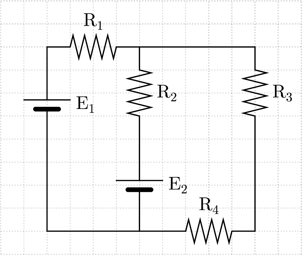
circuit2.gle
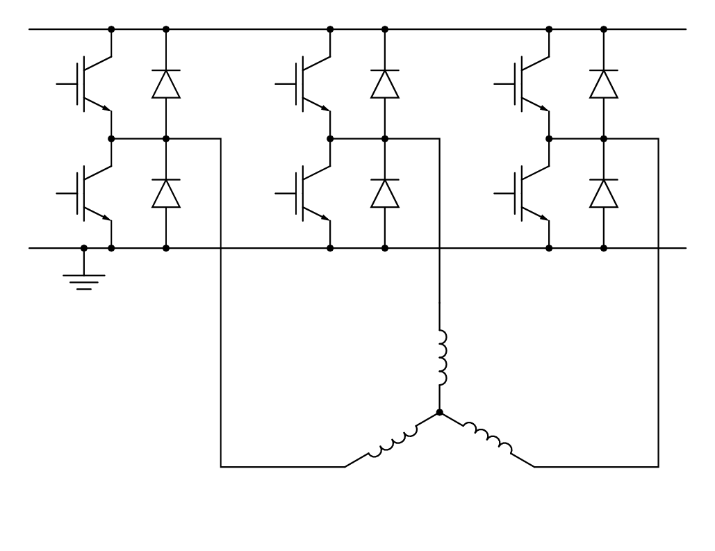
circuit2.gle
! Three phase inverter

size 13 10

include "electronics.gle"

begin scale 0.5 0.5

   set lwidth 0.05 cap round

   ! Draw the DC Link
   amove 1 19
   rline 24 0

   ! Draw Ground
   amove 1 11
   rline 2 0
   @connection
   @ground
   rline 22 0

   ! Transistors
   for i = 0 to 16 step 8
      for j = 0 to 4 step 4
     amove 2 13
     rmove i j
     @igbt ""
     rmove 2 1
     rline 0 1
     rmove 0 -3
     rline 0 -1
     rmove 2 4
     @diode_vu ""
      next j
   next i

   ! Connection po int s
   amove 4 11
   for i = 0 to 16 step 8
      for j = 0 to 8 step 4
     amove 4 11
     rmove i j
     @connection
     rmove 2 0
     @connection
      next j
   next i

   ! Machine windings
   amove 12 15
   rline 4 0
   rline 0 -6
   @inductor_v 0 ""
   @connection
   starx = xpos()
   stary = ypos()
   begin rotate -30
      @inductor_h 0 ""
   end rotate
   rmove 4*cos(torad(30)) -4*sin(torad(30))
   end_y = ypos()
   aline 24 end_y
   aline 24 15
   rline -4 0
   amove starx stary
   begin rotate 210
      @inductor_h 0 ""
   end rotate
   rmove -4*cos(torad(30)) -4*sin(torad(30))
   aline 8 end_y
   aline 8 15
   rline -4 0
end scale
circuit3.gle
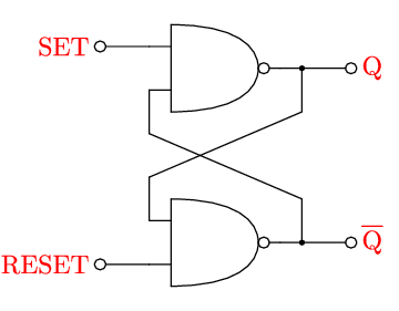
circuit3.gle
! Example of logic gate use: SR Flip-Flop

size 4.5 3.5

include "electronics.gle"

sub overline str$ dy
    gsave
    begin name ov
        write str$
    end name
    amove pointx(ov.tl) pointy(ov.tl)+dy
    aline pointx(ov.tr) pointy(ov.tr)+dy
    grestore
end sub

begin scale 0.25 0.25

set lwidth 0.05 hei 1.2 font rm cap round

! Radius of end terminals
termrad = 0.25; x0 = 4.7

! Reset input
amove x0 2
rmove -termrad 0
circle termrad
rmove -2*termrad 0
set just RC color red
text RESET
set color black
rmove 3*termrad 0
rline 2 0

! Set input
amove x0 12
rmove -termrad 0
circle termrad
rmove -2*termrad 0
set just RC color red
text SET
set color black
rmove 3*termrad 0
rline 2 0

! Top NAND Gate
@nand
rmove 0 -2
rline 0 -2
rmove 0 -2
rline 0 -2
! Bottom NAND Gate
@nand

! Interconnections
rmove 6 -1
rline 1 0
@connection
rline 0 2
rline -7 3
rmove 0 -2
rline 7 3
rline 0 2
@connection
rline -1 0
rmove 1 0

! Top Output
rline 2 0
rmove termrad 0
circle termrad
rmove 2*termrad 0
set just LC color red
text Q
set color black

! Bottom Output
rmove 0 -8
set color red
@overline Q 0.2
set color black
rmove -2*termrad 0
circle termrad
rmove -termrad 0
rline -2 0

end scale
circuit4.gle
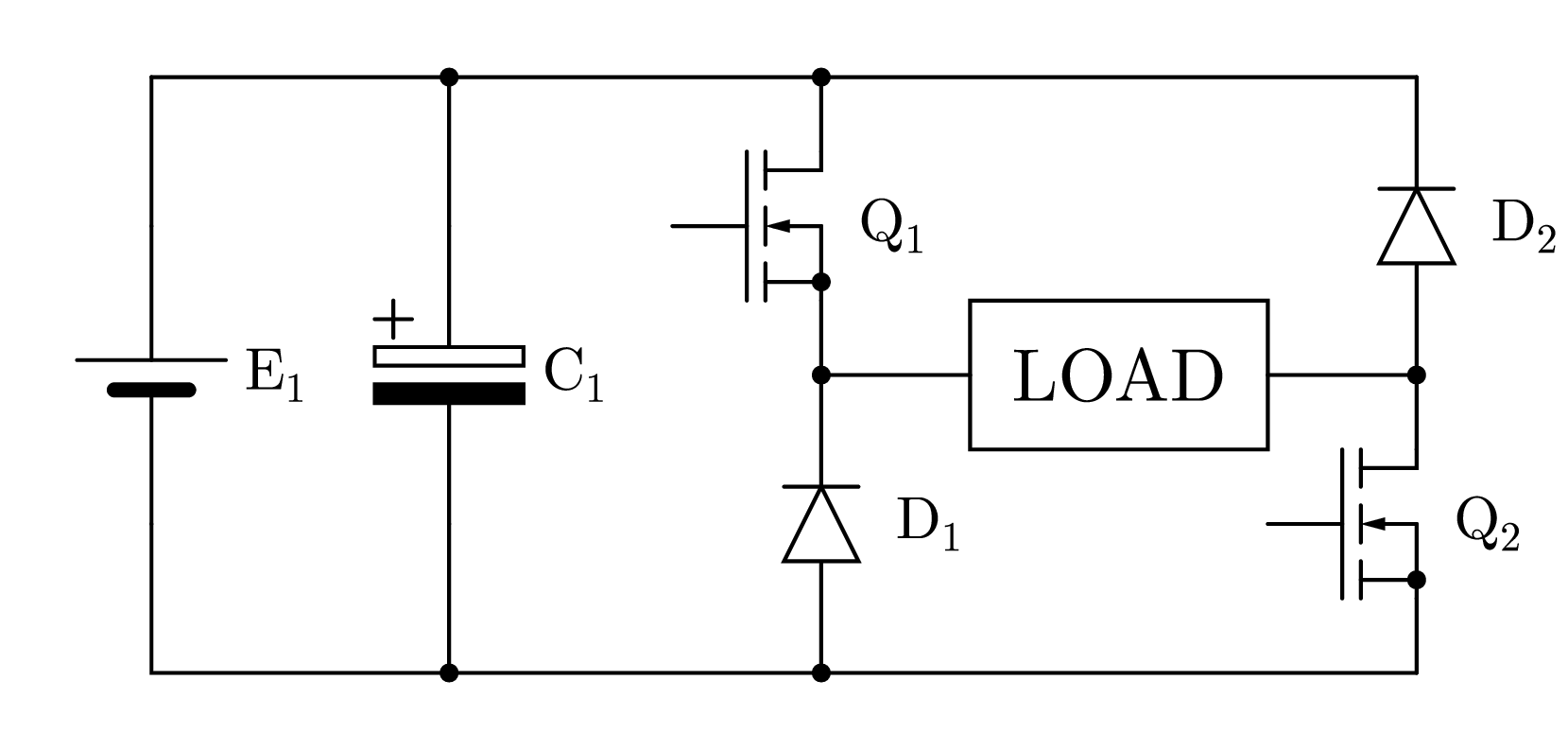
circuit4.gle
! An H-Bridge

! Set the page size
size 21 10

include "electronics.gle"

set lwidth 0.05 cap round

! Draw a grid if the line below is uncommented
!@drawgrid xscale

! Top left of diagram
amove 2 9
gsave

! Battery leg
rline 0 -2
@cell_v "E_1"
rline 0 -2

! Ground plane
rline 17 0

! Return to top left
grestore

! Power to cap leg
rline 4 0
@connection
rline 0 -2
@p_capacitor_vt "C_1"
rline 0 -2
@connection

! Back to power rail
rmove 0 8

! Power to First Leg
rline 5 0
@connection
rline 0 -1
rmove -2 -1
@n_mosfet "Q_1"
rmove 2 -1
rline 0 -1
@connection
@diode_vu "D_1"
@connection

! Back to Power rail
rmove 0 8

! Power to second leg
rline 8 0
@diode_vu "D_2"
@connection
rline 0 -1
rmove -2 -1
@n_mosfet "Q_2"
rmove 2 -1
rline 0 -1

! Back to right hand side of load
rmove 0 4

! Connections to load
rline -2 0
rmove -4 0
rline -2 0
rmove 2 -1

! Load
box 4 2
rmove 2 1
set just CC hei 1
text LOAD
h-bridge.gle
h-bridge.gle
! An H-Bridge

size 13 11
include "electronics.gle"

set lwidth 0.05 cap round font psh

! Draw a grid if the line below is uncommented
drawgrid 1

! Top left of diagram
amove 2.0 9.0

! Battery leg
gsave
rline 0 -0.5
cell_v "E_1"
rline 0 -3.5
rline 5 0
rresistor_h R_4
grestore

rresistor_h R_1

gsave
rresistor_v R_2
cell_v "E_2"
grestore

rline 5 0
rresistor_v R_3
rline 0 -4